cesmith5600
Active Member
I am trying to bring an old Scott Stereomaster 388 back to life. Lots of issues but the one I need help most with right now is a 120Hz signal that I detected while signal tracing for other issues. You can see this in the attached pic "Pin11 L and R copy" Pin 11 refers to my labeling of various measurements points on the PC-TD1 Tone control/Driver board (pic "Tone_Driver Schematic Numbered copy") Note there are two of these boards in the 388, one for the left and one right channel. Pin 11 on the tone control/driver board schematic shows signal coming off the collector of Q6 to the output transistors, to the filter capacitor C9 (or C109 depending on channel) and then to the speaker mains. Measuring signal at pin 11 with a 300mA 1000Hz input signal through the Aux inputs shows both left and right channel signal levels at ~800mVdc (full volume) at a signal frequency of ~120Hz. As a note, Q6 on both channels tested bad and was replaced previously with a 2N3019 (recommended from posts on another forum)
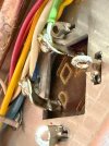
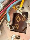
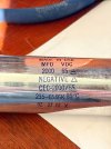
I have read that a 120Hz signal often comes from failed filter capacitors or filter caps not grounded properly. As part of the resurrection work, C9 and C109 Cans were restuffed with 2200uF (stock is 2000 but none were available) axial lead electrolytics of the appropriate voltage rating. I made sure to connect the leads of the new caps to the appropriate terminals of the old can (marked on the side of the can - see pic) and the negative side wires to the appropriate Can terminals. You can see in the attached schematic that the negative side cap and wires lead to the speaker terminal fuses. These wires are color coded and can be followed from the negative side cap terminal to the fuses. I am confident of the appropriate polarity connection. I have double checked this. Since there was no additional grounding of the negative side terminal to the capacitor can, I assume that none is needed. Correct me if I am wrong!! I have attached pics of the original wiring. You can also see in these pics that the Cans are twist tab locked into the chassis mounts. Note that pin 11 is upstream of the signal path to the filter caps so it could be some other issue entirely. The 2N3019 transisitors I replaced for the Q6 transisitors on the tone control/driver board, for example. Anyway I would appreciate some expert advice. Thank you.
I have read that a 120Hz signal often comes from failed filter capacitors or filter caps not grounded properly. As part of the resurrection work, C9 and C109 Cans were restuffed with 2200uF (stock is 2000 but none were available) axial lead electrolytics of the appropriate voltage rating. I made sure to connect the leads of the new caps to the appropriate terminals of the old can (marked on the side of the can - see pic) and the negative side wires to the appropriate Can terminals. You can see in the attached schematic that the negative side cap and wires lead to the speaker terminal fuses. These wires are color coded and can be followed from the negative side cap terminal to the fuses. I am confident of the appropriate polarity connection. I have double checked this. Since there was no additional grounding of the negative side terminal to the capacitor can, I assume that none is needed. Correct me if I am wrong!! I have attached pics of the original wiring. You can also see in these pics that the Cans are twist tab locked into the chassis mounts. Note that pin 11 is upstream of the signal path to the filter caps so it could be some other issue entirely. The 2N3019 transisitors I replaced for the Q6 transisitors on the tone control/driver board, for example. Anyway I would appreciate some expert advice. Thank you.