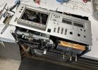
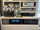
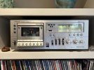
Let me start by saying I think this machine is worth the effort if is is otherwise in good shape. I have mine hooked to the McIntosh C-33, MC 2205 and various speakers including Vandersteen 1b and Dahlquist D-10’s, and it sounds fantastic.
That said, it is not a job for the timid or impatient. Others have said it is one of the worst decks to change the belts on. I don’t know, but looking at how unfriendly this one is, I would not disagree.
So it is probably helpful if you have dug around in some electronic gear before. I’m outlining the steps that I took, some tools I found helpful and with photos to try and show what I’m talking about at various stages. The belts in this deck had turned into some version of black tar goo. This required a lot of cleaning that was the most time consuming part of the job. It is messy and goes a bit slow, but satisfying when you finally are done. Seriously the cleaning took 50% of the time I spent on this.
Besides the regular assortment of standard tools, here are some that made this easier/possible:
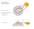
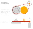
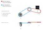
Capstan Drive flat belt (#7 in service manual) Hitachi PN 6357146 Turntable Needles PN FBS10.2
Other drive belt (#8) Hitachi PN 6354031 Turntable Needles SMB6.5
Sensing Belt (#37) Hitachi PN 6354381 Turntable Needles SBO6.0
Flywheel Belt (#39) Hitachi PN 3654451 Turntable Needles SBR4.6
The first two on this list are drive belts on the back side of the transport. The last two are used to drive the counter on the front side of the machine. #39 goes on the back of a take-up spindle to an intermediate pulley and the other (#37) goes from the intermediate to the back of the counter.
Steps to get to the belts:
1 - Remover the top cover screws (two on each side, and three in the in the back. Note the one odd screw in the back goes into the top position.
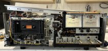
After the cover is off, this is what I saw. I did not unsolder any wires, but I did unplug several connectors. You will be able to get to what you need by making enough slack in the wiring and gently pulling boards and wiring to various places out of the way. Now is when you start taking lots of photos. I shot over 45 photos in the course of this and found myself referring back to many of them when I was reassembling and trying to reroute cables to their original position or figure out how a bracket I took off actually fit. I also labeled every screw and kept them with brackets they held etc. There are not going to be that many but it really saves time on reassembly. An old muffin tin is a big help for this.
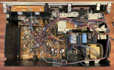
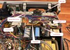
2- Cut all the wire ties you can find in the bundle over the transport and expose the “Plug Board” that sits on the top of the transport and under all the cables. You will be cutting the wire ties on the bundle of wire going to the left also, might as well get them now. There are two connectors on the Plug Board. Unplug and label them. You will remove this board later.
3- Remove the green ground wire coming from the back of the chassis to the bracket on the transport frame.
4 - Remove the two screws holding the “Control Board.” This is the vertical board behind the transport with a screw in each corner using fiber washers (on front and back sides of the board). This board also has a block of foam rubber at the top right glued to the board and a bracket. Separate the foam from the bracket. The bottom of the board is just tabbed into a slot in the plastic case.
5 - Pull this board up some and unplug and label the three connectors on the left edge. Now you can pull the board up and unwind the blue wire from around the cap that goes over to the 120V section (not sure if they are all like this but mine was). Unplug the connector near the middle of the board. Pay attention to the orientation as I think it would be possible to plug this in 180 deg out. You should be able to rotate and set this PCB over on the left side in the cassis out of the way. Cut any wire ties that are not letting you do this.
6 - Remove the back light for the cassette. It is the black plastic thing just behind the front cover, and is held by the screw on the right end and trapped by a bracket on the left. Remove the bracket with three screws completely. The light should now lift straight up and can be pulled to one side.
7- Now you can remove the “Plug Board.” It has a single screw on the left and a tab on the right. Pull it out of the way to see the rear cover of the transport.
8 - Now remove the bracket that the right side of the “Plug Board” was slotted into.

9- Now you can remove the Motor bracket with two screws on the vertical face of the bracket and if your flat belt is still on, unhook it from the motor pulley. Mine was not still attached and it had turned to goo wrapped around the motor drive pulley.
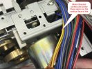
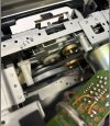
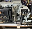
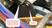
10- The rear plate with the flywheel supports are now exposed and two screws hold it at the top are run into white Nylon posts. The bottom of this bracket fits into a slot in the base (similar to the Control Board PCB). When you remove the left screw note the funny metal part that is free after you pull the screw out. No idea what this is for, but it went under another axle in the mechanism. See Photo below. With both screws removed lift out the back plate, and now you can see all of the capstan pulleys.
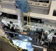
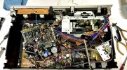
11- The transport should look like this now. You can see some old speaker wire I used to hold the bundle of cables out of the way. The motor is sitting in the lower right and the Control Board rotated and is laying to the left on top of the Main PCB.
That said, it is not a job for the timid or impatient. Others have said it is one of the worst decks to change the belts on. I don’t know, but looking at how unfriendly this one is, I would not disagree.
So it is probably helpful if you have dug around in some electronic gear before. I’m outlining the steps that I took, some tools I found helpful and with photos to try and show what I’m talking about at various stages. The belts in this deck had turned into some version of black tar goo. This required a lot of cleaning that was the most time consuming part of the job. It is messy and goes a bit slow, but satisfying when you finally are done. Seriously the cleaning took 50% of the time I spent on this.
Besides the regular assortment of standard tools, here are some that made this easier/possible:
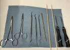
- Metal Dental Picks. I have a set of dental picks that I got from Harbor Freight that are handy for cleaning the goo off of pulleys and in particular, the hook shapes are great for pulling a belt over a pulley you would otherwise not be able to reach with your fat fingers. That is the situation with most of these pulleys.
- Bamboo kabob skewers from the grocery store. The pointy end is good for cleaning the bottom of small pulley grooves, and the other end I carved into a flat scraper. The bamboo is a hardwood and it holds up well and the length helps to reach the flat capstan pulleys where my belts had fused onto the surface. On another skewer I carved a shallow notch into the flat so I could use it to push a belt down under the bottom of a pulley you could not otherwise reach.
- Rubber gloves – use them like they are free. I realized that the goo just magically gets everywhere and after my gloves got even a little on them I was transferring it to all the wrong places. Just toss out the gloves often and put on another pair. Pro tip, use the blue ones. The black I usually wear made seeing how much tar was on them difficult.
- Hemostats – I’ve had these so long I don’t remember where I got them, but they came in handy. Amazon has them of course. I would also sometimes grab a Q-tip with one to reach into a tight spot, or to retrieve a piece of old belt.
- Alcohol (90% is best) and lots (and lots) of Q-tips, and shop paper towels.
- Service manual from Hifi Engine.
- White grease. Like a dab is all you’ll need.
- A pack of small wire ties. The little ones.
Capstan Drive flat belt (#7 in service manual) Hitachi PN 6357146 Turntable Needles PN FBS10.2
Other drive belt (#8) Hitachi PN 6354031 Turntable Needles SMB6.5
Sensing Belt (#37) Hitachi PN 6354381 Turntable Needles SBO6.0
Flywheel Belt (#39) Hitachi PN 3654451 Turntable Needles SBR4.6
The first two on this list are drive belts on the back side of the transport. The last two are used to drive the counter on the front side of the machine. #39 goes on the back of a take-up spindle to an intermediate pulley and the other (#37) goes from the intermediate to the back of the counter.
Steps to get to the belts:
1 - Remover the top cover screws (two on each side, and three in the in the back. Note the one odd screw in the back goes into the top position.
After the cover is off, this is what I saw. I did not unsolder any wires, but I did unplug several connectors. You will be able to get to what you need by making enough slack in the wiring and gently pulling boards and wiring to various places out of the way. Now is when you start taking lots of photos. I shot over 45 photos in the course of this and found myself referring back to many of them when I was reassembling and trying to reroute cables to their original position or figure out how a bracket I took off actually fit. I also labeled every screw and kept them with brackets they held etc. There are not going to be that many but it really saves time on reassembly. An old muffin tin is a big help for this.
2- Cut all the wire ties you can find in the bundle over the transport and expose the “Plug Board” that sits on the top of the transport and under all the cables. You will be cutting the wire ties on the bundle of wire going to the left also, might as well get them now. There are two connectors on the Plug Board. Unplug and label them. You will remove this board later.
3- Remove the green ground wire coming from the back of the chassis to the bracket on the transport frame.
4 - Remove the two screws holding the “Control Board.” This is the vertical board behind the transport with a screw in each corner using fiber washers (on front and back sides of the board). This board also has a block of foam rubber at the top right glued to the board and a bracket. Separate the foam from the bracket. The bottom of the board is just tabbed into a slot in the plastic case.
5 - Pull this board up some and unplug and label the three connectors on the left edge. Now you can pull the board up and unwind the blue wire from around the cap that goes over to the 120V section (not sure if they are all like this but mine was). Unplug the connector near the middle of the board. Pay attention to the orientation as I think it would be possible to plug this in 180 deg out. You should be able to rotate and set this PCB over on the left side in the cassis out of the way. Cut any wire ties that are not letting you do this.
6 - Remove the back light for the cassette. It is the black plastic thing just behind the front cover, and is held by the screw on the right end and trapped by a bracket on the left. Remove the bracket with three screws completely. The light should now lift straight up and can be pulled to one side.
7- Now you can remove the “Plug Board.” It has a single screw on the left and a tab on the right. Pull it out of the way to see the rear cover of the transport.
8 - Now remove the bracket that the right side of the “Plug Board” was slotted into.
9- Now you can remove the Motor bracket with two screws on the vertical face of the bracket and if your flat belt is still on, unhook it from the motor pulley. Mine was not still attached and it had turned to goo wrapped around the motor drive pulley.
10- The rear plate with the flywheel supports are now exposed and two screws hold it at the top are run into white Nylon posts. The bottom of this bracket fits into a slot in the base (similar to the Control Board PCB). When you remove the left screw note the funny metal part that is free after you pull the screw out. No idea what this is for, but it went under another axle in the mechanism. See Photo below. With both screws removed lift out the back plate, and now you can see all of the capstan pulleys.
11- The transport should look like this now. You can see some old speaker wire I used to hold the bundle of cables out of the way. The motor is sitting in the lower right and the Control Board rotated and is laying to the left on top of the Main PCB.