


exwhyzed
Active Member
Hi All,
Thanks to this site (and also avionic), I was able to follow along and repair a non-working left channel of a Harman Kardon 330B. When i picked up the unit, I never paid attention to the sound as it only worked through one side of the headphones at the time. So i can't tell if it had a crummy sound beforehand.
I replaced the large main capacitor, the capacitors and transistors on the amp board, and the board right beside it, and all parts on the two power supply boards underneath.
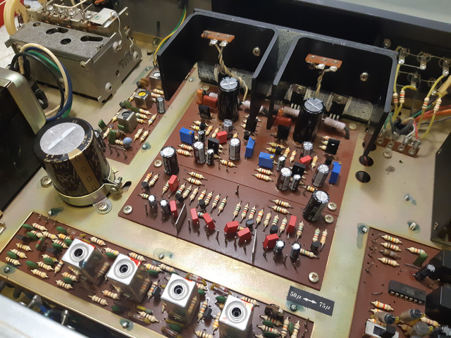
But now I've created a couple of new problems.
1. There is no longer power to the AM or FM board. This was working perfectly before. I get sound on both channels when i use the AUX input. but its totally dead, not even the signal meter moving, when i choose AM or FM.
I took out each part of the primary power supply board and tested them and they are fine. I even put back in the old transistor and diode but still nothing.

2. The sound of the unit sounds coloured in a weirdish way. like 5% reverb has been added...highs a bit rolled-off. Is this because i need to follow through and swap out the green polyester capacitors on the bass/treble tone board as well?
These capacitors were never mentioned in the (dlucy) guide that i was following, but I read about them from another post, where someone commented that swapping them out to newer films caps brightened the sound.
Could this be happening because i have yet to do the Idling Adjustment and DC Balance adjustment to the unit? I can only do the first one myself. and will have to take it to a technician with an oscilliocope to do the second.
Any insights and help would be much appreciated!
Thanks to this site (and also avionic), I was able to follow along and repair a non-working left channel of a Harman Kardon 330B. When i picked up the unit, I never paid attention to the sound as it only worked through one side of the headphones at the time. So i can't tell if it had a crummy sound beforehand.
I replaced the large main capacitor, the capacitors and transistors on the amp board, and the board right beside it, and all parts on the two power supply boards underneath.
But now I've created a couple of new problems.
1. There is no longer power to the AM or FM board. This was working perfectly before. I get sound on both channels when i use the AUX input. but its totally dead, not even the signal meter moving, when i choose AM or FM.
I took out each part of the primary power supply board and tested them and they are fine. I even put back in the old transistor and diode but still nothing.
2. The sound of the unit sounds coloured in a weirdish way. like 5% reverb has been added...highs a bit rolled-off. Is this because i need to follow through and swap out the green polyester capacitors on the bass/treble tone board as well?
These capacitors were never mentioned in the (dlucy) guide that i was following, but I read about them from another post, where someone commented that swapping them out to newer films caps brightened the sound.
Could this be happening because i have yet to do the Idling Adjustment and DC Balance adjustment to the unit? I can only do the first one myself. and will have to take it to a technician with an oscilliocope to do the second.
Any insights and help would be much appreciated!

