• The move to the new server is done. There are some software and database maintenance updates in process. This has us passing the hat around to help out. We appreciate any donations. Seriously, even a dollar helps. The payment page may be found here - https://www.audiokarma.org/support.html

HK 450 with very low Bias, should I be concerned?

Donguri

Active Member
Hi all,
I have a Harman Kardon 450 that I really like, but I've always felt that the left channel is kind of weaker/thin than the right, reading up on DC offset and Bias I finally gathered some courage to give it a try to adjust the DC offset for the first time.
The trimpots were a bit flaky but managed to get both channels down bouncing between -4mV to 4mV after 15 minutes.

I also noticed that the Left channel had been worked on, one of the two output transistors had been replaced and also the Left Bias trimpot seemed to been replaced.

Next I followed the service manual to measure the Bias and according to it the Bias should be measuring 33 mV however when measuring this is what I got:

Left Output transistors:
Nec D587 (not A) & T B688 (This one was the replaced one)
Measuring 12 mV across emitters

Right Output transistors:
Nec D587A & Nec B617A
Measuring 3.5 mV across emitters

I actually thought the Right channel have been sounding good but after seeing the measurements I started to wonder if it´s way off of what it should sound like?
Also is too low Bias bad for the speakers?
Since the Dc offset trimpots were a bit flaky I'm not sure if I should try to mess with the Bias trimpots, is it really necessary?
Edit in 2021: After one year I've become a bit wiser, please DO NOT attach the probes as my depicted picture down below. HK450 service manual states to test at Emitters and I´ve seen others mistaken this as well, but at page 8 "Alignment Points" it clearly shows that they meant the Emitter resistors. Well live and learn :)
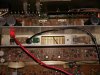
20201122_153545.jpg
Oh, English is not my native language so please excuse any mistakes.
Thank you.
 
Last edited:
Register to hide this ad
Hello. Low bias can cause "crossover distortion" and that would be audible.

If you feel confident and you know what you are doing, I'd adjust it to the factory specs. But check if the emitter resistors are the right value (if somebody used 0.33 instead of 0.22, or something like that, the mV readings are different). Also, check if the manual is telling to measure across 1 resistor, or across 2 resistors.

the way you are measuring is VERY DANGEROUS. I'd find a point electrically connected to the emitters, but without risking to short the transistors (usually the emitter resistors).
In your case (measuring like the pict), I'd be extremely cautious, and POWER OFF THE UNIT AND UNPLUG IT FROM THE WALL before moving the probes. Even like that, you have a risk, a capacitor still charged could burn a transistor. So, act as if the unit is powered, without shorting anything to the heat-sink-
 
Hello Elnaldo and thank you for your reply.

Appreciate the caution, that DID sound scary, I did power it down between the times I hooked up the mini grab probes as recommended by many here, but reading your comments that might not have been enough. So if I understand you correctly, the risk of creating an connection to the heat-sink or any of the other legs are one of the big risks?
I'm in the process of learning these kind of things so all of your warnings were very welcome.

I tried to follow the way it´s described in the SM and it told me to measure between the transistor emitters so thought that was the way to do it.
HK 450 Bias setting.png

When you mention the emitter resistor do you mean the one resistor in the middle between the Left Output transistors called R450?
(Or maybe you mean R454 & R452? They seem to be connected to the emitters.)
Measure it for 0.22 ohm correct?
HK 450 Left Output.png
If it was you how would you measure Bias the safest way if you look at the pictures I supplied?

I think I could adjust it to factory specs if I'm careful, again I'm a novice, but I do have a trim pot tool and a simple Dim Bulb Tester so maybe that could help prevent any disasters.
 
Hello Elnaldo and thank you for your reply.

Appreciate the caution, that DID sound scary, I did power it down between the times I hooked up the mini grab probes as recommended by many here, but reading your comments that might not have been enough. So if I understand you correctly, the risk of creating an connection to the heat-sink or any of the other legs are one of the big risks?
I'm in the process of learning these kind of things so all of your warnings were very welcome.

I tried to follow the way it´s described in the SM and it told me to measure between the transistor emitters so thought that was the way to do it.
View attachment 2044572

When you mention the emitter resistor do you mean the one resistor in the middle between the Left Output transistors called R450?
(Or maybe you mean R454 & R452? They seem to be connected to the emitters.)
Measure it for 0.22 ohm correct?
View attachment 2044626
If it was you how would you measure Bias the safest way if you look at the pictures I supplied?

I think I could adjust it to factory specs if I'm careful, again I'm a novice, but I do have a trim pot tool and a simple Dim Bulb Tester so maybe that could help prevent any disasters.
Here is an edited photo of yours. I hope it is easy to understand..

HK 450 Left Output.jpg
 
Here is an edited photo of yours. I hope it is easy to understand..

View attachment 2044724

Thank you Skywatcher, that was very easy to understand, much appreciated!
I´ll test it and post the results.

So as a rule of thumb, should one always test the Bias (even with other amps/receivers) at the emitter resistors, even if the SM says to measure it at the transistors? Maybe it´s already implied and understood by an experienced tech.
 
the replacement transistors are a mismatch ...
The complementary NPN transistor to the 2SB688 is the 2SD712.

Wow, Thank you Petehall,
That was really good to know, I was worried that it might have been the case, it just didn't look right to me.
Is it possible that it is because of that the sound sounds different between left and right and not because of the Bias setting?

Do you know if the 2SB688 would be the appropriate replacement for the original B617(A?)?
Or are there any more suitable options to make the channels as alike as possible?
I´m kind of new to this so I'm not sure what to look for when comparing..
 
Thank you Skywatcher, that was very easy to understand, much appreciated!
I´ll test it and post the results.

So as a rule of thumb, should one always test the Bias (even with other amps/receivers) at the emitter resistors, even if the SM says to measure it at the transistors? Maybe it´s already implied and understood by an experienced tech.
If you can get to the emitters easier than the resistors, it makes no difference. They connect directly to the same points in the photo if you follow the traces on the board. Do whichever is easier and safer.
 
I've replaced those type of trim pots in the past. Even cleaning them with contact cleaner, they can still be flaky. Marantz used that type of trim pot and after trying to adjust them, I just replace them. They never seemed to stay put once adjusted. The manual does say to adjust the bias with the output transistors instead of the emitter resistors.
The mismatched outputs in the one channel could cause problems. Maybe pull one leg of the emitter resistors, the big white bricks, and make sure they are in spec? Odd that there is three big capacitors. Usually you see only two for a direct coupled amplifier. Seeing three i thought capacitor coupled. But the manual does have instructions to set DC offset.
 
If you can get to the emitters easier than the resistors, it makes no difference. They connect directly to the same points in the photo if you follow the traces on the board. Do whichever is easier and safer.

Got it, that's good to know for future measuring.
I did a 15 minute test on the left channel emitter resistors as per your excellent explanation and it measure around 14 mV.
20201124_181856.jpg
If you look at the green B688 transistor you can see the mod a previous tech must have done, not sure if it is a good job or not.

@Lavane
Agree, I had been thinking about putting new trim pots just for the sake of giving me a little peace of mind, What trim pot did you use in your Marantz and was it an perfect fit? Not too familiar with soldering but got all the equipment to make it happen, just have to gather courage.

I can see four big capacitors in there, two for each channel it seems.
 
MJE15032 and MJE15033 might be better replacements . you would have to drill and tap the heat-sink or make hold down bars for them .
finding the original outputs might prove difficult .
 
I use Bourn trimmers. Either single turn or multi turn. There a few types. A coue single turn type looks simar to the original, and the other looks like a small blue rectangle with an adjustment screw on one end. They come in single turn, or multi turn. I kind of like the mti turn pots, it can be easier to dial them in. You would need to know the value of the original. Bourn trimmers can be found at Mouser or Digikey.
 
MJE15032 and MJE15033 might be better replacements . you would have to drill and tap the heat-sink or make hold down bars for them .
finding the original outputs might prove difficult .

Thank you.
I did a quick search on Mouser, they had those ones but only with the letter G attached (MJE15032G), are they the same?

Sounds like a bigger project than I might be able to pull off right now, but I'm hoping maybe later.
Wonder how much disadvantage would it be to leave it as is? And should I try to change the Bias to spec even with unmatched transistors or is it running in danger of creating problems?
 
Last edited:
Thank you.
I did a quick search on Mouser, they had those ones but only with the letter G attached (MJE15032G), are they the same?

Sounds like a bigger project than I might be able to pull off right now, but I'm hoping maybe later.
Wonder how much disadvantage would it be to leave it as is? And should I try to change the Bias to spec even with unmatched transistors or is it running in danger of creating problems?
Yes, the "G" means they meet the "lead free" status, that's all.
 
Got it, that's good to know for future measuring.
I did a 15 minute test on the left channel emitter resistors as per your excellent explanation and it measure around 14 mV.
View attachment 2044870
If you look at the green B688 transistor you can see the mod a previous tech must have done, not sure if it is a good job or not.

@Lavane
Agree, I had been thinking about putting new trim pots just for the sake of giving me a little peace of mind, What trim pot did you use in your Marantz and was it an perfect fit? Not too familiar with soldering but got all the equipment to make it happen, just have to gather courage.

I can see four big capacitors in there, two for each channel it seems.
If that 2SB688 transistor is working fine, just leave it be. It is overkill so you will probably never blow it. :D
 
yes but is it playing nicely with the other one ?
That is why I said "if"...:D Besides, it looks like it should be fine..
Type Designator: 2SB688
Material of Transistor: Si
Polarity: PNP
Maximum Collector Power Dissipation (Pc): 80 W
Maximum Collector-Base Voltage |Vcb|: 120 V
Maximum Collector-Emitter Voltage |Vce|: 120 V
Maximum Emitter-Base Voltage |Veb|: 5 V
Maximum Collector Current |Ic max|: 8 A
Max. Operating Junction Temperature (Tj): 150 °C
Transition Frequency (ft): 5 MHz
Forward Current Transfer Ratio (hFE), MIN: 55

Type Designator: 2SB617A
Material of Transistor: Si
Polarity: PNP
Maximum Collector Power Dissipation (Pc): 70 W
Maximum Collector-Base Voltage |Vcb|: 120 V
Maximum Collector-Emitter Voltage |Vce|: 100 V
Maximum Emitter-Base Voltage |Veb|: 5 V
Maximum Collector Current |Ic max|: 6 A
Max. Operating Junction Temperature (Tj): 150 °C
Transition Frequency (ft): 7 MHz
Forward Current Transfer Ratio (hFE), MIN: 60
 
That is why I said "if"...:D Besides, it looks like it should be fine..
Type Designator: 2SB688
Material of Transistor: Si
Polarity: PNP
Maximum Collector Power Dissipation (Pc): 80 W
Maximum Collector-Base Voltage |Vcb|: 120 V
Maximum Collector-Emitter Voltage |Vce|: 120 V
Maximum Emitter-Base Voltage |Veb|: 5 V
Maximum Collector Current |Ic max|: 8 A
Max. Operating Junction Temperature (Tj): 150 °C
Transition Frequency (ft): 5 MHz
Forward Current Transfer Ratio (hFE), MIN: 55

Type Designator: 2SB617A
Material of Transistor: Si
Polarity: PNP
Maximum Collector Power Dissipation (Pc): 70 W
Maximum Collector-Base Voltage |Vcb|: 120 V
Maximum Collector-Emitter Voltage |Vce|: 100 V
Maximum Emitter-Base Voltage |Veb|: 5 V
Maximum Collector Current |Ic max|: 6 A
Max. Operating Junction Temperature (Tj): 150 °C
Transition Frequency (ft): 7 MHz
Forward Current Transfer Ratio (hFE), MIN: 60
looks better on paper than in the picture . i suppose a simple check might be check voltages across each emitter resistor to see if one is working harder than the other . saying that i have often see correct pairs differing a bit with no apparent problems .
 
Back
Top Bottom