• The move to the new server is done. There are some software and database maintenance updates in process. This has us passing the hat around to help out. We appreciate any donations. Seriously, even a dollar helps. The payment page may be found here - https://www.audiokarma.org/support.html

HK 630 Receiver - FM Issues and Amp Adjustments

David_NC

Super Member
I picked up this 630 Twin Powered receiver about a week ago, along with the Concept 4.5D pictured with it (not pictured is the non-functional 4.5D that was also included). The HK is in near mint condition cosmetically, other than needing a little cleaning. Functionally, it's also good, other than the tuner doesn't seem to work on FM. It does receive stations, according to the meter, but there's no sound on FM or FM stereo, regardless of the muting setting. I've downloaded the manuals for it but am unsure of where to start diagnosing the FM issue.
Also, I'm seeing a bit of DC in the speaker outputs and would like to try to adjust that lower, and I figured I should check the bias, too. I'm not seeing either of those in the manual. If anyone has any tips or suggestions on any of these things, I'd definitely appreciate hearing them.
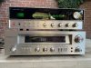
HK 630 & Concept 4.5D.jpg
 
Register to hide this ad
Also, I'm seeing a bit of DC in the speaker outputs and would like to try to adjust that lower, and I figured I should check the bias, too. I'm not seeing either of those in the manual.

No adjustment for DC offset, according to the schematic I'm looking at. If you think the offset is worth worrying about, you could try selecting transistors as replacements for the 2SA564As in the power amps. Or if one of the really smart AKers who knows how to fiddle with diff amp operating points comes along - I think ecluser is one - you could take that advice to the bank.

Bias adjustment is under the header "PREDRIVER/DRIVER ADJUSTMENT". Don't bother with most of the section - just go right to the "using a DC millivoltmeter" step, and note that this is done with "no signal output". (If it was me, I would do it with no speakers connected, or speaker switches turned off. Be careful.

No particular idea about the FM. If it was on my bench, I guess I'd start by seeing if there was any signal at pin 1 of the MPX board. It should be the "composite audio" signal - mostly mono audio, but with some higher-frequency signals sprinkled in with the stereo information.
 
where to start diagnosing the FM issue
A good place to start is verifying power supply voltages are getting to there proper destinations. Are you using some kind of external antenna ?
 
If the meter is working, then I'd start looking for a problem just past that.

General steps to get you started:

  1. DeOxit (and sand, if needed) pads 5 and 6 on the function selector, the STEREO/MONO switch, and the FM MUTING switch.
  2. Remove and verify VR101 is working, hasn't partly fallen apart, and is providing the full range of 1-250k ohms.
  3. Verify you have full voltage arriving at the FM MUTING board. Where B6 comes in you should be reading 12v.
  4. Verify you have full voltage arriving at the FM STEREO board. Where B5 comes in you should be reading 14v.
  5. Replace all the electrolytic caps on the FM MUTING and FM STEREO boards. You could remove each one and test it, looking for failure or drift, but then you might as well replace each with new, known-good caps.
  6. Remove and verify VR901 is working, hasn't partly fallen apart, and is providing the full range of 1-10k ohms.
  7. Remove and verify VR302 is working, hasn't partly fallen apart, and is providing the full range of 1-10k ohms.
 
Also, I'm seeing a bit of DC in the speaker outputs and would like to try to adjust that lower,
How do you define "a bit"? Small adjustments of the output offset voltage can be had by adjusting the value of the input pair emitter resistor, R603 and R623. Schematic shows 8.2k - you could try adjusting it over the range of perhaps 7.5k to 9.1k. Anything further than that and you are changing more than just the output offset.
 
It does receive stations, according to the meter, but there's no sound on FM or FM stereo, regardless of the muting setting.
So you get left-right movement on the tuning meter when tuning through a station? Does the stereo indicator light come on when tuned to a stereo station?
 
How do you define "a bit"? Small adjustments of the output offset voltage can be had by adjusting the value of the input pair emitter resistor, R603 and R623. Schematic shows 8.2k - you could try adjusting it over the range of perhaps 7.5k to 9.1k. Anything further than that and you are changing more than just the output offset.
I don't recall exactly, as I figured it'd need to be adjusted regardless. It was somewhere in the 45-50mV range though.

So you get left-right movement on the tuning meter when tuning through a station? Does the stereo indicator light come on when tuned to a stereo station?
Tuning meter moves when tuning. There's no stereo light and no sound on FM, though AM seems to work.

Thanks.
 
[offset] It was somewhere in the 45-50mV range though.
Might be able to tweak that by adjusting the emitter resistor, but 50mv is low enough to not cause a problem.
Tuning meter moves when tuning. There's no stereo light and no sound on FM, though AM seems to work.
So the FM front end is working up through the FM detector, so the fault is beyond that. dlucy offered some good suggestions and you could go ahead and try those. Certainly do check for proper voltage at B5. Also, or alternately, you could add a temporary jumper between terminal 1 and terminal 5 (or 5') of the stereo decoder board. See if you get audio (on one channel) if you do this.
 
Might be able to tweak that by adjusting the emitter resistor, but 50mv is low enough to not cause a problem.
So the FM front end is working up through the FM detector, so the fault is beyond that. dlucy offered some good suggestions and you could go ahead and try those. Certainly do check for proper voltage at B5. Also, or alternately, you could add a temporary jumper between terminal 1 and terminal 5 (or 5') of the stereo decoder board. See if you get audio (on one channel) if you do this.
Thanks much. I'll be checking this receiver out more this weekend, hopefully. Between what @dlucy posted and this, I should have a few specifics to check. I'll post back with my findings. I really wish I had a service manual for this as good as what I have for my old Sony TA-2000!
 
A good place to start is verifying power supply voltages are getting to there proper destinations. Are you using some kind of external antenna ?

If the meter is working, then I'd start looking for a problem just past that.

General steps to get you started:

  1. DeOxit (and sand, if needed) pads 5 and 6 on the function selector, the STEREO/MONO switch, and the FM MUTING switch.
  2. Remove and verify VR101 is working, hasn't partly fallen apart, and is providing the full range of 1-250k ohms.
  3. Verify you have full voltage arriving at the FM MUTING board. Where B6 comes in you should be reading 12v.
  4. Verify you have full voltage arriving at the FM STEREO board. Where B5 comes in you should be reading 14v.
  5. Replace all the electrolytic caps on the FM MUTING and FM STEREO boards. You could remove each one and test it, looking for failure or drift, but then you might as well replace each with new, known-good caps.
  6. Remove and verify VR901 is working, hasn't partly fallen apart, and is providing the full range of 1-10k ohms.
  7. Remove and verify VR302 is working, hasn't partly fallen apart, and is providing the full range of 1-10k ohms.
Controls have been cleaned again with DeOxit
VR's all seem good. I did not remove them, but they all appear to work correctly (i.e. change values smoothly on my meter).
All voltages mentioned in the SM have been checked; specified voltages > measured voltages are listed below.
FM IF Board 12V > 12.48V
AM Circuit Board 12V > 10.57V
FM MPX Board 14V > 13.9V
EQ Amp Board 21V > 20.3V
Power Supply Board:
-30V > -30.5V
+30V > +30.4V
+30V > +30.6V
-30V > -30.3V​
Power Supply (tuner / preamp) 21V > 20.8V
Tone Amp Circuit Board 21V > 20.3V
Muting Circuit Board 12V > 12.47V
Regulator Circuit Board:
Input (+B3) 21V > 20.2V
FM Stereo PCB (+B5) 14V > 13.89V
Funct. Switch, Front-end, Muting PCB (+B6) 12V > 12.51V​
 
I guess my next question is are those voltages close enough to accept as OK and move on to additional troubleshooting? Function switch seems to be working; it controls inputs and switches on and off various boards based on what function is selected. Mono and muting switch have also been cleaned, and my meter indicates that they are making and breaking contact as appropriate.
If an oscilloscope is helpful for additional testing, I do have one (an HP Agilent 54645D). I've played with it a few times but am by no means well versed in their usage!
 
I guess my next question is are those voltages close enough to accept as OK and move on to additional troubleshooting? Function switch seems to be working; it controls inputs and switches on and off various boards based on what function is selected. Mono and muting switch have also been cleaned, and my meter indicates that they are making and breaking contact as appropriate.
If an oscilloscope is helpful for additional testing, I do have one (an HP Agilent 54645D). I've played with it a few times but am by no means well versed in their usage!

All those voltages are fine, except the AM board, so next step, as I suggested, is get those 40+ year old ecaps replaced. In my opinion....
 
Could try adding the jumper as I mentioned in post #8, or put that scope on the MPX board terminal 1 and see what you see. Should be audio there when tuned to a station.
 
All those voltages are fine, except the AM board, so next step, as I suggested, is get those 40+ year old ecaps replaced. In my opinion....
Getting together a parts list now and checking my current stock of caps. I'll start with the preamp / tuner PS board and FM boards first.

Could try adding the jumper as I mentioned in post #8, or put that scope on the MPX board terminal 1 and see what you see. Should be audio there when tuned to a station.
I'll do these while I'm waiting on parts.

Thanks for the suggestions!
 
Could try adding the jumper as I mentioned in post #8, or put that scope on the MPX board terminal 1 and see what you see. Should be audio there when tuned to a station.
A 'scope on MPX board terminal 1 shows no changes in the display when it's tuned to a station, based on the dial and on the tuning meter. I'm not sure how to describe the signal on my 'scope. It's just a sine wave that disappears when the receiver is turned off, and it only changes when I touch the unit anywhere. If it matters, it's reading 12 volts.
 
Sounds like you might be seeing 60 Hz hum. Is the scope probe ground connected to the receiver chassis? Let's back up to the output of the FM IF board - terminal 5. Measure the DC voltage at that point. It should go from a bit positive through zero to a bit negative as you tune through a station. Be sure the 'muting' is turned off and connect the scope to terminal 5, scope ground to the receiver chassis. Tune to a station and see if you can see any audio. You will probably want the scope sweep rate set to around 1ms/div.
 
Sounds like you might be seeing 60 Hz hum. Is the scope probe ground connected to the receiver chassis? Let's back up to the output of the FM IF board - terminal 5. Measure the DC voltage at that point. It should go from a bit positive through zero to a bit negative as you tune through a station. Be sure the 'muting' is turned off and connect the scope to terminal 5, scope ground to the receiver chassis. Tune to a station and see if you can see any audio. You will probably want the scope sweep rate set to around 1ms/div.
You were correct about the ground; it had come disconnected. With it connected, things look much different!
MPX board pin 1 definitely shows changes when I tune to a station and off the station
The FM IF board shows exactly what you described. Plus, I can tell as I approach a station, tune it, and then tune past it.
 
So it sounds like the audio is getting to the MPX board. Try that jumper between the MPX terminal 1 and terminal 5 (or 5'). That will bypass the MPX board. I suspect the MC1307 is bad, but want to be sure before I send you off to order a part.
 
So it sounds like the audio is getting to the MPX board. Try that jumper between the MPX terminal 1 and terminal 5 (or 5'). That will bypass the MPX board. I suspect the MC1307 is bad, but want to be sure before I send you off to order a part.
I'll do it this afternoon and report back. Thanks much!
 
So it sounds like the audio is getting to the MPX board. Try that jumper between the MPX terminal 1 and terminal 5 (or 5'). That will bypass the MPX board. I suspect the MC1307 is bad, but want to be sure before I send you off to order a part.
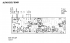
I know where terminal 1 is on the MPX board, but I'm unsure about terminal 5. I think it might be the one shown bottom left (in the pic below).
upload_2022-7-29_18-24-15.png
My 'scope shows what appears to be an audio signal that changes as the tuning knob is turned on terminal 5. If that's not it, please correct me. ;)
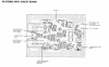
Another thought... would I get mono audio if I jump between 'FM composite signal input' upper right (of the pic below) and the left or right audio output terminals on the left side?
upload_2022-7-29_18-32-38.png
 
Back
Top Bottom