

You are using an out of date browser. It may not display this or other websites correctly.
You should upgrade or use an alternative browser.
You should upgrade or use an alternative browser.
HK 730 FM Stereo Alignment
- Thread starter A Sound Mind
- Start date


A Sound Mind
Reckless Tinkerer
Define LPF please. There's a 0.22uF cap between those pins.LPF on Pins 8 and 9?
And pin 8 has a 1K resistor going to the collector of Q315.
A Sound Mind
Reckless Tinkerer
No. just listening to a strong stereo station and hearing it kick in. But I have a 100MHz scope and would like to know how this test is done. I don't have an FM stereo generator though.How did you verify you have stereo coming out of this thing in FM? Tape out with a scope in X/Y mode?

Ylli
Super Member
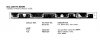
Did you change that stereo indicator lamp? The one in the parts list says "6.3 V 40 mA". (earlier I said 8 volt, that was incorrect). If you need to drop the series resistor to 25 ohms to get the lamp to light, it is drawing **way** too much current. The Stereo indicator lamp output of the IC is current limited at 75 mA.
A Sound Mind
Reckless Tinkerer
I selected one from spares that lit at 8 volts. I didn't check its current draw though.Did you change that stereo indicator lamp? The one in the parts list says "6.3 V 40 mA". (earlier I said 8 volt, that was incorrect). If you need to drop the series resistor to 25 ohms to get the lamp to light, it is drawing **way** too much current. The Stereo indicator lamp output of the IC is current limited at 75 mA.
View attachment 2783780

LPF, Low Pass Filter.
Connect your scope to the outputs of the tuner or record out. Put the scope in X-Y mode. Mono should be a 45 degree flat line, lower left to upper right if both channels are equal. Stereo will be the same 45 degree angle but expand in the middle showing the difference between left and right. This will make sure Stereo is actually working and is actually fun to watch.
Craig
Connect your scope to the outputs of the tuner or record out. Put the scope in X-Y mode. Mono should be a 45 degree flat line, lower left to upper right if both channels are equal. Stereo will be the same 45 degree angle but expand in the middle showing the difference between left and right. This will make sure Stereo is actually working and is actually fun to watch.
Craig
Ylli
Super Member


Ylli
Super Member
While you are considering the lamp issue, let's check if the IC is still working OK on that pin.
Connect a 1K resistor (or that 1K pot set to maximum resistance) between Pin 1 and pin 6 of the IC. Put the voltmeter on pin 6. With no station tuned in you should see about 12 volts at pin 6. Tuned to a stereo station you should see < 2.0 volts.
Connect a 1K resistor (or that 1K pot set to maximum resistance) between Pin 1 and pin 6 of the IC. Put the voltmeter on pin 6. With no station tuned in you should see about 12 volts at pin 6. Tuned to a stereo station you should see < 2.0 volts.
Last edited:

dr*audio
Fish fingers and custard!
I think you said you replaced the stereo lamp. What did you use; voltage and current rating of the lamp? Maybe you have a 300mA lamp in there. Should be like 40mA.I tried this. No light. Tacked in a 1k pot from the light side of R302 to gnd. Light came on at around 25Ω.
How does the IC trigger the lamp driver? What external components that support this IC can I examine? It has a good power supply and there is 19KHZ on pin 10.
Another thing to consider is the right channel takes 1-2 seconds longer to come up than the left.
A Sound Mind
Reckless Tinkerer
The lamp that was in there drew 175mA @ 6.3 volts! I replaced it with one rated @ 30mA and it's working!
But now after messing around with the various pots on the board, I need to dial back in FM stereo as much as possible without using an FM stereo generator.
I do have the following: Heath FMO-1 FM test oscillator (mono), Heath IG-102 signal generator, Tektronix 100MHz scope, Tektronix DMM, VTVM, HP function generator w/AM and FM sweep, frequency counter.
But now after messing around with the various pots on the board, I need to dial back in FM stereo as much as possible without using an FM stereo generator.
I do have the following: Heath FMO-1 FM test oscillator (mono), Heath IG-102 signal generator, Tektronix 100MHz scope, Tektronix DMM, VTVM, HP function generator w/AM and FM sweep, frequency counter.
Ylli
Super Member
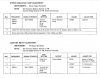
Well, I see VR301, VR302, VR351, VR352, and VR353. If you didn't adjust any of these, then don't readjust them now.
VR301: This is the de-mux free running frequency adjust. You already set that to 19.00 KHz.
VR302: Stereo separation. Don't know how you can accurately adjust this without a stereo generator. By ear or centered.
VR351 and VR352: These affect the way the meter responds to signal strength. Looks like this unit has an unusual meter in that it is a 'quieting' meter instead of an actual signal strength meter. (The manual says that an input of 20 uV should indicate "6" on the meter, but I don't believe either of your RF generators have calibrated outputs). Adjust them iteratively until the meter is responding in a way that appears correct to you.
VR353: This sets the threshold where the receiver feels the signal is strong enough to switch to stereo. When the signal is too weak, it should automatically switch back to mono. (The manual spec is at an input of 32 uV) Basically you will want to tune in a weak signal and adjust VR353 so that the stereo light just goes out. Decodes stereo on relatively strong signals, and reverts to mono (stereo lamp goes out) when you tune to a signal that is short of full quieting. Pick the point you think is best. (Looks like the adjustment of VR351 will affect this, so do the VR351/VR352 settings first.)
VR301: This is the de-mux free running frequency adjust. You already set that to 19.00 KHz.
VR302: Stereo separation. Don't know how you can accurately adjust this without a stereo generator. By ear or centered.
VR351 and VR352: These affect the way the meter responds to signal strength. Looks like this unit has an unusual meter in that it is a 'quieting' meter instead of an actual signal strength meter. (The manual says that an input of 20 uV should indicate "6" on the meter, but I don't believe either of your RF generators have calibrated outputs). Adjust them iteratively until the meter is responding in a way that appears correct to you.
VR353: This sets the threshold where the receiver feels the signal is strong enough to switch to stereo. When the signal is too weak, it should automatically switch back to mono. (The manual spec is at an input of 32 uV) Basically you will want to tune in a weak signal and adjust VR353 so that the stereo light just goes out. Decodes stereo on relatively strong signals, and reverts to mono (stereo lamp goes out) when you tune to a signal that is short of full quieting. Pick the point you think is best. (Looks like the adjustment of VR351 will affect this, so do the VR351/VR352 settings first.)
dr*audio
Fish fingers and custard!
Here's how you can get a FM stereo generator on the cheap:
Buy a FM Stereo modulator for use in a car. They are used to play a CD player or similar through your car's radio.
I have a Belkin that I use for alignment when I need a synthesized source to align a synthesized tuner. It will have a left and right input, so to adjust the separation, only connect one channel and adjust for minimum signal on the opposite channel.
Something like this will work.
https://www.amazon.com/Belkin-TuneCast-Mobile-FM-Transmitter/dp/B00008SB1D?th=1
Buy a FM Stereo modulator for use in a car. They are used to play a CD player or similar through your car's radio.
I have a Belkin that I use for alignment when I need a synthesized source to align a synthesized tuner. It will have a left and right input, so to adjust the separation, only connect one channel and adjust for minimum signal on the opposite channel.
Something like this will work.
https://www.amazon.com/Belkin-TuneCast-Mobile-FM-Transmitter/dp/B00008SB1D?th=1

kasbah512
Member
This is exactly what I just did. I opted for one with adjustable frequency output.Here's how you can get a FM stereo generator on the cheap:
Buy a FM Stereo modulator for use in a car. They are used to play a CD player or similar through your car's radio.
I have a Belkin that I use for alignment when I need a synthesized source to align a synthesized tuner. It will have a left and right input, so to adjust the separation, only connect one channel and adjust for minimum signal on the opposite channel.
Something like this will work.
https://www.amazon.com/Belkin-TuneCast-Mobile-FM-Transmitter/dp/B00008SB1D?th=1
I also have a HA1156 in my unit and the replacement i ordered is the HA1156W, but i cant get the pilot frequency high enough. it tops out at 18.8 khz.
I thew the tuning WAY out of wack chasing a ghost, and now im trying to get it back to at least play in stereo. Some of the adjustments have no visible changes on my oscilloscope, but the more i adjust, the worse it gets. The manual says it MUST be under .3% THD to work correctly if im reading that right. I have a marantz 2215B on my bench.
dr*audio
Fish fingers and custard!
What are you using to measure the frequency? You could be loading down the circuit. If you have a frequency counter and the input impedance is 50 Ohms, that is too low. Some of them have an impedance switch or alternate 1M Ohm input. Sometimes there is a 50 Ohm resistor across the input jack that you can remove. If your scope measures frequency, use that, with a 10X probe.This is exactly what I just did. I opted for one with adjustable frequency output.
I also have a HA1156 in my unit and the replacement i ordered is the HA1156W, but i cant get the pilot frequency high enough. it tops out at 18.8 khz.
I thew the tuning WAY out of wack chasing a ghost, and now im trying to get it back to at least play in stereo. Some of the adjustments have no visible changes on my oscilloscope, but the more i adjust, the worse it gets. The manual says it MUST be under .3% THD to work correctly if im reading that right. I have a marantz 2215B on my bench.
Failing that, you can tune to a known good station and adjust the PLL pot to the middle of the range where the stereo light comes on.
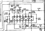
If none of that works, the IC could be junk or an external component may be bad. Pin 14 of the IC goes to components that set the frequency.
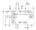
So if C303 is bad, the frequency would be off.
kasbah512
Member
The gadget on the left just saved the day.
I was using an oscilloscope as a frequency counter, but it would display 19.0 kz, and was likely not high enough resolution. With this transmitter device I turned the source all the way down to just send the pilot signal and used some finesse. If i remember correctly i heard it "click" into place on my headphones.What are you using to measure the frequency? You could be loading down the circuit. If you have a frequency counter and the input impedance is 50 Ohms, that is too low. Some of them have an impedance switch or alternate 1M Ohm input. Sometimes there is a 50 Ohm resistor across the input jack that you can remove. If your scope measures frequency, use that, with a 10X probe.
Failing that, you can tune to a known good station and adjust the PLL pot to the middle of the range where the stereo light comes on.
If none of that works, the IC could be junk or an external component may be bad. Pin 14 of the IC goes to components that set the frequency.
