• The move to the new server is done. There are some software and database maintenance updates in process. This has us passing the hat around to help out. We appreciate any donations. Seriously, even a dollar helps. The payment page may be found here - https://www.audiokarma.org/support.html

HK Citation II pushes out speakers when powering off

What type of coupling capacitors does the circuit use? If they are old oil-impregnated paper, aka paper in oil coupling capacitors, they may be leaking (:) not oil, but current). You may also notice significant excursion of the speaker cone.
It has all new JFX metallized poly film coupling caps. So most likely no leaking coupling caps. The tech did nice work.
 
What type of coupling capacitors does the circuit use? If they are old oil-impregnated paper, aka paper in oil coupling capacitors, they may be leaking (:) not oil, but current). You may also notice significant excursion of the speaker cone.
I would have thought the McShane upgrade would have replaced these older, DC-leaky-prone caps.

For sure, the unit should have newer poly caps.

The other thing is the age of those main electrolytic caps in the power supply. It is possible that one or more could have dried out. Not sure of the date of the power supply upgrade.

:idea:
 
It has all new JFX metallized poly film coupling caps. So most likely no leaking coupling caps. The tech did nice work.
Okay, no worries with the coupling caps.

When was that McShane power supply mod done? More than 15-20 years ago?

Thanks!
 
Okay, no worries with the coupling caps.

When was that McShane power supply mod done? More than 15-20 years ago?

Thanks!
I'd have to say all the work was most likely done in the last 10 years.

I noticed a difference between the bias adjustment circuits on each channel.

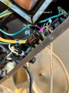
Channel B has 100v 100uf cap running from the left terminal of the bias adjustment pot for V8 to a new terminal board with a couple resistors. One resistor terminates at the right terminal of the bias pot and the other resistor goes to the bias selector switch.

Channel A does not have the capacitor on the bias pot and has one less resistor in the circuit. (speaker pump problem channel)

I'm pretty sure these circuits have to do with bias adjustment :) Just not sure why one is different from the other and if the difference could be causing the power imbalance on shut off.
 

Attachments

  • Channel A.jpg
    Channel A.jpg
    102 KB · Views: 24
  • Channel B.jpg
    Channel B.jpg
    101.7 KB · Views: 25
Jim may be the guy to ask about this. I believe he's still supporting Citation II stuff, just retired from selling tubes.
That's a good call. I was going to send him an email to see if I could get the directions/schematics for the kit that was installed for reference.
 
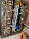
The bias components for Jim's kits are are mounted on a terminal strip that's mounted where the original selenium rectifier are, on the bracket that holds the main power supply caps and opposite end from the HV diodes. So I have my doubts that this has McShane upgrades.
 
I think if you increase the capacitance on both sides of the bias circuitry, you'll solve your PS timing issue.
 
The bias components for Jim's kits are are mounted on a terminal strip that's mounted where the original selenium rectifier are, on the bracket that holds the main power supply caps and opposite end from the HV diodes. So I have my doubts that this has McShane upgrades.
To be more clear, I was referring to the bias adjustment pots on the back of the amp. The power section is definitely a McShane kit and has the diodes where the selenium rectifier used to live.
 
I would have thought the McShane upgrade would have replaced these older, DC-leaky-prone caps.

For sure, the unit should have newer poly caps.

The other thing is the age of those main electrolytic caps in the power supply. It is possible that one or more could have dried out. Not sure of the date of the power supply upgrade.

:idea:
Right, that’s sorted. The Sprague 160P, also known as ‘Black Beauty’, is a sturdy capacitor; check for any dried solder joints. The bias supply is shared by both channels but can be adjusted individually; I assume the amplifier was working properly before.
Also check the cathode bypass capacitors and feedback loop components.
 
I think if you increase the capacitance on both sides of the bias circuitry, you'll solve your PS timing issue.
That's what I'm thinking as well...see if I have a spare cap of that value, or maybe remove it. I still don't understand why only one side would have it though :dunno:
 
That's what I'm thinking as well...see if I have a spare cap of that value, or maybe remove it. I still don't understand why only one side would have it though :dunno:
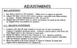
In case you missed the bias procedure, check the attached file
 

Attachments

  • IMG_0669.jpeg
    IMG_0669.jpeg
    153.6 KB · Views: 11
Since the bias supply is shared by both channels, and the two bias circuits run in parallel, I think there would only be one filter cap. I'm not sure where you'd add another one (not physically, but within the bias circuit itself).
 
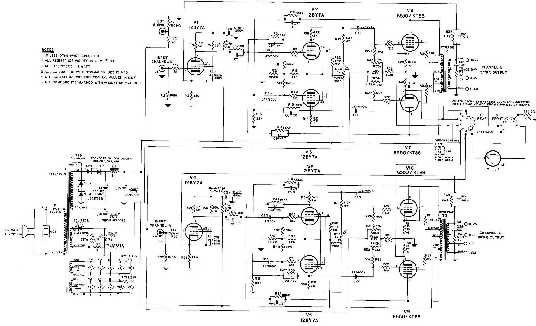
As for that cap in the bias supply - per the schematic, both channels are connected to it - no need for a second one. Seems to me that this would have to come from an asymmetrical part of the circuit, because the supply voltage (as it's dropping) is the same on both halves of the push-pull output and phase inverter. That would mean the first amplifier stage. One way to divide this would be to connect a clip lead from R10 to R70, or R45 to R71 to essentially disconnect that first stage. Does it still do this at power off? And you could do the same with the output tube grids if it does.

Don't expect adding a bleeder to change anything - the tubes draw much more current than the resistor will, and drain the caps almost completely before they cool.. But still a good idea - sometimes you do run a amp for testing without tubes in it - and those caps will stay charged for a week or so...
 
Last edited:
Since the bias supply is shared by both channels, and the two bias circuits run in parallel, I think there would only be one filter cap. I'm not sure where you'd add another one (not physically, but within the bias circuit itself).
I wouldn’t add another cap. Simply adjust the bias and AC balance as described in the manual.
 
I'm not going to add another cap. Honestly I'm not super confident on my schematic reading on this amp, so I'm not adding or removing anything as of now, other than adding the bleeder resistor.

Where on the schematic is the best place to add a bleeder resistor?
 
Since the bias supply is shared by both channels, and the two bias circuits run in parallel, I think there would only be one filter cap. I'm not sure where you'd add another one (not physically, but within the bias circuit itself).
As for that cap in the bias supply - per the schematic, both channels are connected to it - no need for a second one. Seems to me that this would have to come from an asymmetrical part of the circuit, because the supply voltage (as it's dropping) is the same on both halves of the push-pull output and phase inverter. That would mean the first amplifier stage. One way to divide this would be to connect a clip lead from R10 to R70, or R45 to R71 to essentially disconnect that first stage. Does it still do this at power off? And you could do the same with the output tube grids if it does.

Don't expect adding a bleeder to change anything - the tubes draw much more current than the resistor will, and drain the caps almost completely before they cool.. But still a good idea - sometimes you do run a amp for testing without tubes in it - and those caps will stay charged for a week or so...
I'm seeing now on the schematic that the bias adjustment is connected across both channels. Thanks for pointing that out.
 
I'm not going to add another cap. Honestly I'm not super confident on my schematic reading on this amp, so I'm not adding or removing anything as of now, other than adding the bleeder resistor.

Where on the schematic is the best place to add a bleeder resistor?
Traditionally, the resistor is after the last capacitor in the power supply rail. From positive to ground.

98ac2acc-3180-492a-9b85-808cc659ab23.jpg


The bleeder resistor would go after (right of) C15 — Positive rail to ground.

If you feel uncertain about doing this yourself, can you have the tech that did the McShane mods add the bleeder? :idea:
 
Back
Top Bottom