• The move to the new server is done. There are some software and database maintenance updates in process. This has us passing the hat around to help out. We appreciate any donations. Seriously, even a dollar helps. The payment page may be found here - https://www.audiokarma.org/support.html

HK Hot Rod nears restoration completion

Nice job Don, and those are some rugged looking windings. We need to get you a megger so you can test TX varnish insulation. Also, on TXs like that with six holes going through the lams, I drill the bells and use 6 bolts evenly tightened and with nylon washers. Oh, 3M makes a motor / TX varnish that will cure at room temp. If I see what looks like moisture in windings with the megger, I pull the bells and bake at 175 degrees for a few hours and re-test. When it's gone, and the megger reads infinity, I will dob some varnish on any spots that need it (like where the paper is gone on yours). I don't know what they used for varnish back then, but it was damn good stuff.:yes:
 
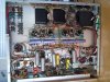
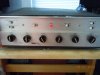
Here are some pictures of the final assembled product with the Heyboer power transformer.
The 12AU7 to 6CG7 conversions are complete with AC fils. All resistors are replaced. All capacitors except for out of the sonic path ceramics are replaced, including rebuilding the RIAA circuit.

Unfortunately, the new power transformer is too high to put the cover on properly. I'll go to home depot, get some perforated metal and make a custom one with a cutout where the the power transformer can stick out.

Inside view:
attachment.php


Top view:
attachment.php


Cover on view:
attachment.php
 

Attachments

  • finalinsides.jpg
    finalinsides.jpg
    109.1 KB · Views: 1,139
  • finaltop.jpg
    finaltop.jpg
    76.8 KB · Views: 791
  • finalcover.jpg
    finalcover.jpg
    58.2 KB · Views: 541
Last edited:
I still have a bit of voltage tweaking balancing and testing around the 6L6GCs to accomplish, but that'll be it for this one.
There's no buzz, no hum, and no noise. Both top and bottom are extended without compromising the midrange.
Now it's time to use it - regularly.
 
Went through the final adjustment throes yesterday.

I found that the voltage dropping resistor one level down from B+ was providing the wrong voltage one level down from B+ and was too high in a relative way to B+.
Back Story:
I typically tweak the power supply voltage dropping resistor values to bring the voltages in line with today's 123Vac line voltage.
So, since the voltage varies, I'll typically run a Variac up to 123 at the input.

I have two CL-60 thermisters on each side of the primary winding of the power transformer. I'll test the voltage there. Right now it's at 118.2Vac.

So, then I check B+. In this case B+ is just shy of 400Vdc where 410 is called for in the schematic.

Then there's a (rated value) 1k ohm 3 watt resistor to drop to the next voltage level down from B+ to go to the screen on pin 4.
In a previous tweak with the other power transformer, I'd changed that value to a 330 ohm resistor.
So, the value coming off the output transformers to the highest voltage pin 3 to the plate is about 395.
The voltage coming off the first dropping resistor (330 ohm) was 379 to the pin 4 screen.
That's too high in a relative way. So after measuring a good value using a switching resistor box I have, I substituted in a 500 ohm 10W power resistor I had on hand and the rest of the values fell in line properly. My 770 resistor dropped the voltage too much, dropping the next levels from the power supply too low for my taste.

Then I used the balance control between pairs of output tubes until I got within millivolts of each other on pin 8. Both sets are tubes are now dissipating between 48 and 52 ma.
I did not find a spec of what dissipation should be on a 6L6GC. Does this value sound correct?
Nostalgia Air seems to be gone. I did some online searching but probably didn't dig deep enough. My RCA tube handbook only goes as far as 6L6G.

Actually, I'm pretty new to these big power tubes and can't tell my grid from my screen from my plate, so assistance on terminology would be appreciated.


Voltages at 6L6GC output tubes after a five hour continuous run on wall voltage of 120.4Vac:
Fils 2 & 7 - 6.5Vac
Pin 3 395 Vdc
Pin 4 373 Vdc
Pin 5 -30.5 Vdc
Pin 8 ~500mvdc.

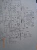
attachment.php


attachment.php
 

Attachments

  • outputschem.jpg
    outputschem.jpg
    54.4 KB · Views: 178
  • outputschemfull.jpg
    outputschemfull.jpg
    61 KB · Views: 174
Last edited:
Don -- Something is not quite adding up with your numbers, but it may all be caught up in terminology.

At one point you indicate that both sets of tubes are (I believe you mean to say) "drawing" between 48 and 52 ma. This implies that each tube within a set is drawing only 24 to 26 ma -- which is much too low.

On the other hand, you indicate that the voltage at pin #8 (cathode) is .5 vdc. This voltage across a 3.3 ohm resistor (common to both output tubes in a given channel) calculates to nearly 152 ma per set, or 76 ma per tube, which is much too high.

Based on the known circuit parameters, the optimum bias should likely be .35 vdc across the 3.3 ohm resistor in each channel. If you were in fact running .5 vdc across this resistor, it would make the amp sound rather restricted.

Let me know if I am understanding your comments correctly regarding this..

Your work looks great!

Dave
 
Yes, the balanced pairs of tubes do draw evenly.
One pair draws .510mv/3.3 ohms and the other pair draws .415 over 3.3 ohms.
So, you're saying they should be about .35 volts?
The negative voltage pin is about -28 at the tubes after the balance circuit. I can't seem to get it more negative than that.
The output of the AC transformer is about 24VAC, not 36, as shown in the schematic. After going through that filtering circuit at the bottom of the schematic, the output is just about -30Vdc. I can't seem to pull it more negative.

Because I changed the wiring of the filaments in the circuit and V3 is now a 6CG7 instead of a 12AU7 powered in series with the two 12AX7s V1 and V2, there's less of a voltage drop at that point and V3 is no longer in series with V1 and V2. Is additional resistance needed to emulate V3 in that circuit to pull it more negative? How much equivalent resistance does a filament add so I can replace it with a resistor?
These are just my late night thoughts. I'll stick a decade box on the fil tomorrow and see what I can see.
That might be it. I'm powering V3 off of the other filament circuit, not the negative bias circuit and the voltage drop is probably not correct anymore.
 
Last edited:
Don -- Yes, ultimately you will want the voltage across the 3.3 ohm resistors to be about .35 to .40 vdc.

Why is the new transformer only delivering 24 vac for the bias/dc heater supply winding? Is this because it is overloaded from trying to operate only two series connected tubes now at (therefore) a higher current flow level than they are designed to operate at (which would happen if one of the tubes was removed from the heater string with a 36 volt winding) or, is it because the new transformer is either wound or spec'd wrong? Either way, having only 24 volts from the winding is the source of the problem in trying to get the correct current draw in the output stage.

If the winding is only delivering 24 vac by design, then a new rectifier circuit will need to be devised to deliver the necessary bias voltage for the output tubes, as 24 vac is simply not enough with the existing design.

Let us know!

Dave
 
I put a power resistor box in series with that DC filament set and got the negative bias voltage right to -36Vdc with a 2500 ohm resistor.
I had a 10W 2500 ohm wirewound resistor and put it in.
Now my two pairs of tubes are running at .32V and .39v.
Would it be best to leave each channel's pairs as is or mix and match and adjust the balance control for each pair again to try and center closer to 35ma?

I'm going to mix and match tomorrow to try and get comparably balanced pairs.

Math test:
For current draw in a balanced pair of tubes, would this math work for dissipation?
pair of tubes voltage at cathode /balanced pair cathode resistor = Sum. Sum/2 would be per tube dissipation in a roundabout way.

So, 320mv/3.3ohms=103.7ma
103.7ma/2 balanced output tubes = ~52 ma/tube.
So, would my dissipation per tube be about 52ma in this example?
 
Last edited:
Don,

Your tubes are consuming about 52mA each, you are correct. Power dissipation rating is somewhat different, because it reflects the how much power a tube can consume while maintaining its specs. Since power P = V*I, your tubes consume 52mA*395V = 20.54W, and therefore, operate well under 30W rating for 6L6GC.

BTW, I have something for you from my trip, give me a call when you have a minute.

Thanks, Paul.
 
Don, it may well be a good idea to mix-and-match the tubes to try and get both sides as close as possible to the same current- then use the balance controls to equal out the two in each pair. Though, I'd listen afterward- and if it sounds better to match the two tubes to each other in each channel, and not WORRY about one channel pulling more total curran than the other- as long as you're well within the dissipation of the tubes, that's completely OK too.

I'm with Paul here- as long as the PS isn't sagging on the B+, 52ma per 6L6GC, @ just under 400v B+, is good.

Regards,
Gordon.
 
Last edited:
By mixing and matching the two sides, and having run up the primary input to 120VAC after the thermisters (or about 123.3VAC in) I got the B+ to the rated 400V.
By mixing and matching the tubes, I got the two sides balanced.
Channel A is running at 33ma
Channel B is running at 37ma.
This is with some old GE 6L6GCs I have.

Wow, this thing has balls!
Bass extension right down there, extended highs, and no loss of midrange. This one's a keeper.
In its present state, it exceeds my Fisher X-101-C integrated sonically, and that's saying something.
I'm very impressed with the clarity, lack of congestion, balance channel-to-channel, quietness and outright muscularity.
Then again, every resistor in the audio path has been replaced with a carbon comp hand-matched between channels, plus it's entirely recapped.
 
Interesting thread. I've wanted to try some 6cg7 on a few projects but haven't gotten to it for a lack of tubes and time.
 
Don -- Were you able to properly power the remaining DC heaters and provide enough bias for the output stage from the new 24 vac bias/heater winding? If so, do you have enough bias range to adequately handle the normal range of bias required for "typical" 6L6 tubes?

One thing you might consider doing is to convert the existing half-wave rectifier system for the bias/heater supply to a full-wave bridge. It will be kinder to the power transformer (less peak current demands), and also develop a little more voltage if that would help.

Dave
 
Dave,
You're very subtle in your suggestions . . . in the best possible way. I might have to change that rectifier, but I may have gotten around it.

Well, I used the amp for a couple of days in my office system and all was well until I decided to try and compare my outboard phono stage, which I'd been using, to the internal recapped and re-resistored internal phono stage in the HK Chorale.
That power resistor, which got the negative bias right where it needed to be, drew all the power out of the circuit and starved the DC filaments (V1 and V2 (plus originally V3) that were supposed to act as the dropping resistors. So, I had no phono and I guess the two 12AX7s were for the phono stage only. The tube shields were on and I hadn't noticed that they were not operating when using the line level inputs, which don't use those tubes.

So, out came the 2500 ohm power resistor and back went the decade box while I tried to find a balance that would provide enough negative bias to put the output tubes in a safe operating range while not starving the dc heater filaments of V1 and V2.
The balance turned out to be between 82 ohms and 220 ohms. I settled on a 5W 150 ohm resistor. That provides just over 12VDC each to the V1 and V2 filaments and still presents about -32Vdc to the balance circuit, which calls for -36Vdc.

So, after remixing and rematching the 6L6GC output tubes, with a 123Vac input (deliberate), I was able to get dissipation for the tube pair in channel A to 42ma and channel b to 45 ma.
That's a little more than ideal according to dcgillespie's suggestions, and I may switch from these GE 6L6GCs to some Russian 6N3CEs, which, as well as being more robust, are fine sounding tubes.
I'll test the internal phono stage vs. the outboard phono stage tomorrow.
 
If I'm reading it right- 63ma @ 400v (on the channel that's .45v)? That's about 25 watts dissipation per tube. GE 6L6GCs will THRIVE in that environment. They're rated at 30 watts, and will take every bit of it. That's about 83% of max dissipation- which is just fine for those.

In fact, I'm running 55ma @ 430v on my 6L6GCs in my Mk 6L6 amps. 24 watts dissipation, and those are Ruby STRs (Chinese). They don't even flinch...

If you reduced the wall voltage to 120v, you'd still be in a good range. As long as those 12.6v input tubes are seeing at least 11.5v on the heaters, they'll be fine. And it would reduce the current in the outputs just a tad...

Regards,
Gordon.
 
Last edited:
Gordon,

I once did a 'project' amp that was kind of a 'clone' to an ST-35. I used some boards supplied by Chart Chong.....OTs and a PT from Hammond supplied by Angela Instruments. As it worked out, the PT had a 6V filament winding....and a 5V filament winding. So, one side of the amp got the 6V while the other side got the 5V. About the only thing I could determine from a 'performance' perspective was that the one side took a few seconds longer to 'warm up' when first turned on. Beyond that....I couldn't tell any difference in the way one side sounded from the other. I had the amp 'checked' by an EE friend out in California....and as he put it...."There are plenty of 'free electrons running around in there' at 5 volts on the heaters......so don't worry about it!' Since then, I've not given that amp a second thought. But, after reading all this on Don's amp.....I keep going back to that imbalance I had on the old Clone amp (which now lives at my son's house in Michigan). I've always wondered.....'Should I fix that....or not?'. Just curious.....any opinion?

Sorry Don.....didn't mean to 'gank' your thread here. You just got me thinkin......

Tom D.
 
I'd have been tempted to wire that 6v winding and 5v winding in series (make 11.3v) and then wire pairs of the tubes, in series. Stuff like 12AX7s and such could just be wired as 12.6v heaters... output heaters in series...

In fact, on my Dyna P2P preamp project, I'm basically doing just that. A 5v winding and a 6.3v winding, in series, then DC bridge rectified, is EASY to get right to 12.6v, with just a modicum of voltage adjustment...

Regards,
Gordon.
 
Tom -- With power tubes, they can be operated at lower heater voltages (within reason), as long as the peak current demands are reduced appropriately. Operating a power tube at reduced heater voltage while still demanding rated peak current capabilities from the tube will damage the cathode rather quickly.

Dave
 
Dave/Gordon,

If I recall, the amp was running about 40 to 50 VDC LOWER than the original ST-35 spec.....which I don't recall right now.....but I seem to recall that if it was something like 330 volts.....the hammond transformer was putting out about 290. Thanks to both of you for the response. My inclination regarding that amp is that since it's at my son's home and he's happy with it......I think I'll just leave well enough alone! TSD
 
Back
Top Bottom