• The move to the new server is done. There are some software and database maintenance updates in process. This has us passing the hat around to help out. We appreciate any donations. Seriously, even a dollar helps. The payment page may be found here - https://www.audiokarma.org/support.html

HK6900 Broken Power Supply Board

Beavs

Active Member
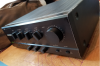
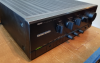
I picked up an "excellent condition, in working order" HK6900 for peanuts from an auction because it looks like an early 90's black box and nothing special so there wasn't much interest in it aside from me. The auction house packed it themselves with a whopping 2 layers of thin bubble wrap and then squeezed it into the tightest box they could find and sent it on it's way to me. Needless to say, it didn't survive the journey.

I had hoped to find someone parting one out but it sounds like this was pretty expensive and pretty rare back in the early 90's so not much for options there. Thanks to @Karl vd Berg he pointed me to @dlucy 's thread on a broken PCB in a Harman Kardon 730
https://audiokarma.org/forums/index...a-broken-pcb-board-and-circuit-traces.881571/
This made me think I can probably salvage this HK6900 (that's a big maybe though, never got to turn it on myself, only have the word of the auction house that was "in working order").

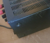
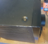
First observations were of some pretty good dings to the outer case (auction photos showed none of this damage):
upload_2021-4-30_9-51-15.png
upload_2021-4-30_9-51-51.png
upload_2021-4-30_9-52-22.png

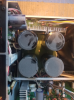
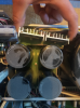
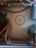
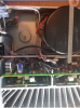
Then pulled the top off and found the snapped power supply board:
upload_2021-4-30_9-54-17.png
upload_2021-4-30_9-54-43.png
upload_2021-4-30_9-55-15.png

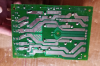
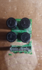
It is split into two main pieces, but the smaller of the two pieces you see above is actually snapped into 5 pieces (two of the smaller breaks still held together by resistor legs) and then the larger piece with the filter caps is spiderwebbed a bit with some broken traces there:
upload_2021-4-30_10-0-39.png
 
Register to hide this ad
So following @dlucy 's lead on this, I went to gluing using the same CA insta-cure glue I think he did:
upload_2021-4-30_10-7-5.png

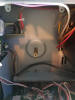
Re-tracing this shouldn't be too painful I'm hoping. My bigger concern is the support of the PCB with those 4 large filter caps on it, but I think I got a plan for it and will welcome any feedback if anybody has a better idea here. The board is supported by the 4 corners and one post right in the middle of the filter caps, but the good news here is there are no real obstructions from those connection points all the way to the top case of the amp, and I have about 3/4" to work with between the top of the filter caps and the top case...ruler placed on transformer just for reference, this thing's a beast 5-1/4" diameter:
upload_2021-4-30_10-11-48.png
upload_2021-4-30_10-12-50.png
upload_2021-4-30_10-14-5.png
upload_2021-4-30_10-15-9.png

So my thoughts here are that the weight of these filter caps is not going to help at all on a glued and retraced PCB. So somehow I need to reinforce this PCB and the drilling and filling with epoxy bridges from the @dlucy thread comments or some of the PCB medic supplies (pricey!) weren't really instilling much confidence. But the good thing that I have going here is that I've got space to work in this amp luckily. I plan to cut and drill a "base" for the PCB out of 1/4" plywood that will sit between the PCB and the 5 original connection points on the amp frame. With the fragility of those points (ie - 2 of 4 corners already snapped), I'll drill some additional holes between the PCB and the plywood to secure those together instead of relying on those two broken corners. I'll probably use some rubber washers between the PCB and plywood at all screw points to an equivalent thickness of the solder points on the bottom of the PCB.

I think it's a doable plan, but I'm entirely open to having holes shot through this if I'm missing something here. My current questions would be as follows:

- Use solid or stranded 12gauge copper for the fat power supply traces?

- Same question but what smaller gauge for the small traces?

- After getting all the bridges soldered in, do I need to coat/insulate these at all? I thought about some of that liquid electrical tape stuff if needed but I don't really think I need to do that on this board.

- Wood. Is this the right choice here or should I be thinking a plastic type of material? I'm not going for pretty, I'm going for functionality.
 
Last edited:
I wouldn't think so.. They were not insulated in the first place.
Avionic! Just so you know, there was no molestation of the wire wrapped pins on this one...they were already soldered on anyway so I don't think it would have made a difference. FYI, the CR-2040 you've helped me so much on is sitting there lonely waiting on some pots and switches to arrive at some point...

Here's the pins on the HK6900. These are what I've been looking for on the CR-2040 pin headers but I still haven't been able to find any (grayish header pieces):
upload_2021-4-30_10-56-7.png
upload_2021-4-30_10-56-34.png
 
I know this sounds low tech, but I'd consider cutting some perf board to match and secure it to the bottom of the circuit board. Maybe use blobs of hot melt to support at key points? (Hotmelt can be reversed. Of course some epoxy would be sturdier.)
 
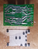
Well I didn't end up using the perf board, thanks for the recommendation though. However, it made me think away from the plywood option and I had a small piece of plexi-glass that I ended up using. I used individual strands from 600V 12ga copper wire, strand counts that were used varied based on what would fit on each of the PCB traces. The narrow traces that were insulated were definitely the hardest but they got done. Here's the retraced/soldered board:
upload_2021-5-4_12-54-16.png

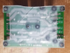
To get enough spacing between the plexi and the PCB to not create stress concentration points at the individual solder nodes (some are higher than others), I ended up using 00 size rubber seats for a water faucet. After cutting/drilling the plexi, I basically placed the rubber seats at points across the PCB that wouldn't be sitting directly on top of the traces (I don't think it would affect anything if sitting on the traces but generally avoided them anyway). The right side of the board in the pic above is the "fragile" side, corners were broken off so I wasn't very confident in the support from just those two screw points and went a bit crazy with the rubber seats on that side of the board. Once placed on PCB, put a small dab of the CA glue on them and then placed the plexi on top...cracked the plexi when sawing but a little CA glue fixed that and it was strong enough to hold the pound or so of this board so I'm not terribly worried about that:
upload_2021-5-4_13-2-7.png
upload_2021-5-4_13-2-36.png
upload_2021-5-4_13-3-12.png
 
There was probably a way to test this board before putting it back into the amp, but I don't have a standalone power supply so I basically just checked continuity between the previously broken traces and all looked good so back in the amp it went:

upload_2021-5-4_13-6-43.png

You wouldn't know it was in there when looking from the top, still plenty of clearance between the top of the filter caps and the outer case. And then came the moment of truth of turning it on. Even if I was successful in repairing the power supply board traces/connections, I already had concerns about what also could have gone wrong that I wasn't seeing because of the main focus on the power supply board. Also, in reading about this amp, it sounded like various owners had issues with it not coming out of protection mode. So, I felt the odds were pretty stacked against me on this turning on or coming out of protection mode. Plugged it into the DBT and it came right on and out of protection mode after about 3 seconds or so. Played some music through headphones, all good. Then through speakers at low volume, all good. So took it off the DBT and started giving it a full run through on by bench speakers (EPI 70C) and I fully expect this to be biased because I'm so pleased with being able to rebuild the power supply board and have it still function, but I think this amp sounds really, really good compared to most other ones I've played through those same bench speakers. I'll get it hooked up to my other main systems and see what I think after that but so far I'm pretty pleased with this thing. Also, gave the faceplate a silver lined frame around the edges to try to blend the damage that was done to the faceplate during shipping...back case will get some some fresh paint too:
upload_2021-5-4_13-19-17.png
upload_2021-5-4_13-19-45.png
 
Last edited:
Back
Top Bottom