falconthrust
New Member
Hello Audiokarmugens,
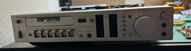
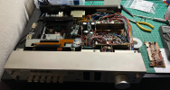
This might be more verbose than needed, however I have been attempting to diagnose an odd issue during the restoration of an interesting Harman/Kardon HK705 tape deck. Cosmetically it is perfect, and so far I have replaced all the belts (which I would suggeest to never attempt to do). I have playback working flawlessly, and was able to test for all types I-IV with no issue. However, in order to get this back in full operation, I need to be able to record! Here is the obligatory tape deck in pieces currently on the bench:
This is where the interesting part comes in. Right channel records perfectly, however the left channel only seems to be outputting highly distorted, low frequency information from the input/music I am attempting to record. Before you jump to conclusions, please do not tell me to DeOxit, if someone tells me to Deoxit I will flip (just kidding, but oxidation on any of the switches, including the long switch that switches between play and record mode, was dealt with thoroughly).
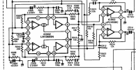
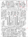
I have tracked down where the degradation in the signal starts, at the LM13600N IC (#IC902) in the following schematic:
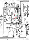
When fed a pure sine wave, the right channel output from pins 10->9 of the IC provide a pure sine wave output, however the right channel 7->8 output appears to be clipping on the bottom part of the waveform. It is a very clean clipping, kind of like the following poorly drawn image:\

I removed the IC to test the diode voltage drops that should be present across pins 10->9 and 7->8, and both test to be the same voltage, as well as the resistance across them. Tested in reverse they both show no leakage.
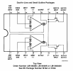
I really want the easy answer to be "replace the LM13600N", however the more I think about the issue the more I fear this may be incorrect. I have a gut feeling that there might be a biasing issue with the input voltage TO the IC, and this is what is causing the clipping to occur. Every single cascading down from this board is a distorted signal, and everything coming into the board is clean/ without any visible signs of distortion. I would think that if there were a voltage biasing issue causing the clipping, it would be present on both the left and right channels as the input buffers' supply voltage to the collector of the NPNs are shared from pin 11 of the IC.
Unfortunately I do not know enough about opamp supply voltage or audio input to figure out where to go from here, my only solutions paths right now seem to be:
1) Recap every electrolytic upstream of the left signal path, which I desperately do not want to do
2) Replace 13600N (with a modern SMT such as a 13700N or NE5517 with an SMT to DIP package adapter)
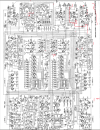
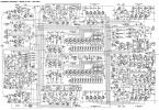
Please Audio karma, you are my only hope! I have attached a clean schematic for your viewing pleasure.
This might be more verbose than needed, however I have been attempting to diagnose an odd issue during the restoration of an interesting Harman/Kardon HK705 tape deck. Cosmetically it is perfect, and so far I have replaced all the belts (which I would suggeest to never attempt to do). I have playback working flawlessly, and was able to test for all types I-IV with no issue. However, in order to get this back in full operation, I need to be able to record! Here is the obligatory tape deck in pieces currently on the bench:
This is where the interesting part comes in. Right channel records perfectly, however the left channel only seems to be outputting highly distorted, low frequency information from the input/music I am attempting to record. Before you jump to conclusions, please do not tell me to DeOxit, if someone tells me to Deoxit I will flip (just kidding, but oxidation on any of the switches, including the long switch that switches between play and record mode, was dealt with thoroughly).
I have tracked down where the degradation in the signal starts, at the LM13600N IC (#IC902) in the following schematic:
When fed a pure sine wave, the right channel output from pins 10->9 of the IC provide a pure sine wave output, however the right channel 7->8 output appears to be clipping on the bottom part of the waveform. It is a very clean clipping, kind of like the following poorly drawn image:\
I removed the IC to test the diode voltage drops that should be present across pins 10->9 and 7->8, and both test to be the same voltage, as well as the resistance across them. Tested in reverse they both show no leakage.
I really want the easy answer to be "replace the LM13600N", however the more I think about the issue the more I fear this may be incorrect. I have a gut feeling that there might be a biasing issue with the input voltage TO the IC, and this is what is causing the clipping to occur. Every single cascading down from this board is a distorted signal, and everything coming into the board is clean/ without any visible signs of distortion. I would think that if there were a voltage biasing issue causing the clipping, it would be present on both the left and right channels as the input buffers' supply voltage to the collector of the NPNs are shared from pin 11 of the IC.
Unfortunately I do not know enough about opamp supply voltage or audio input to figure out where to go from here, my only solutions paths right now seem to be:
1) Recap every electrolytic upstream of the left signal path, which I desperately do not want to do
2) Replace 13600N (with a modern SMT such as a 13700N or NE5517 with an SMT to DIP package adapter)
Please Audio karma, you are my only hope! I have attached a clean schematic for your viewing pleasure.