• The move to the new server is done. There are some software and database maintenance updates in process. This has us passing the hat around to help out. We appreciate any donations. Seriously, even a dollar helps. The payment page may be found here - https://www.audiokarma.org/support.html

HK710 Tuner - No stations. Where to start?

RS-MN

Active Member
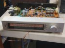
I have an extremely clean HK710 Tuner that was part of a stack which included a HK750 Receiver and HK701 Cassette Deck. The Receiver and Cassette work fine, but the Tuner has no stations.

Backlight to the display works. No signal strength lights when moving the dial, no sound from stations.
Doesn't matter what antenna is used, it's not getting any stations on AM or FM.

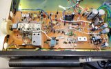
Where to start? :dunno: I don't see any obvious component failure. it all looks like new.
 

Attachments

  • HK710-1.jpg
    HK710-1.jpg
    87.7 KB · Views: 17
  • HK710-2.jpg
    HK710-2.jpg
    146.5 KB · Views: 17
Last edited:
Register to hide this ad
Typically I would look at your power supply voltages first. Will need a manual to locate test points and a multimeter.
 
What PunkerX said, but I'll add that the transistor mounted to the U-channel heat sink near to the largest capacitors is almost surely the pass transistor for a power supply of something like +13VDC. It is a likely suspect, as are the solder joints for it.

If I'm correct, that transistor would be expected to have a voltage closer to +20VDC on its collector (center terminal), and around +13VDC on both of its outer terminals.

But this won't do you much good unless there is access to the solder side of the board in this vicinity. If there is no such access, a repair project might not be worth the effort. But of course that depends on how enthusiastic you are about keeping the stack together.
 
Black lead grounded to Chassis. Red lead on component:

The transistor has 0/-.5/-.5 (outer/center/outer).
I got the board out to a point where I can stand it vertical and solder on it. I've reflowed the solder joints of that transistor and items around it. - No change.

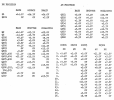
Voltages around the Transistor
D1: 13.4/-.1
D3: 27.1/-.45
Q1 - 27.0/0/0
Q3 - -14.7/-25.7/-15.3
Pin for green wires to display: 13.7V
Pin for Red wires to display: 13.7V

I've ordered some of the larger capacitors and will replace the ones around the Transistor. Maybe the transistor or a cap is bad?
 

Attachments

  • HK710 Voltages.png
    HK710 Voltages.png
    262.4 KB · Views: 4
Last edited:
Q1 - 27.0/0/0

Just as a point of etiquette, you might want to provide a pointer to the manual you are using.

Assuming I'm looking at the same manual, I think the above is the most relevant data, and I think it indicates that either Q1 has failed open, or D4 or C8 has failed shorted.

You could try temporarily jumping a resistor in the vicinity of 1200 ohms across Q1. If the voltage readings that were zero are still zero with this jumper in place, then I think D4 or C8 has failed shorted. My money would be on D4.
 
I downloaded the HK710 Service Manual here: HK710 Tuner Service Manual. HiFi Engine has the same one. I'm not aware of a better one. If there is, please post it or leave a link.

I'll find a resistor and try what you suggested.

Are there any replacements recommended for:
D4 - Zener Diode, RD15EB 14.7V +/- 0.9V
The closest I'm finding are these from internet searches:
"The NEC RD15EB is a 15 V, 500 mW, DO‑35 Zener diode, so the closest direct replacements are standard 15 V / 0.5 W DO‑35 Zeners such as 1N5245B or BZX55C15, provided their tolerance matches the “EB” grade." "If your circuit requires tight tolerance, choose BZX55B15 (2%) or 1N5245C (2%)."
BZX55B15 R0G is available at Mouser


Q1 -F.E.T. 2SK163 (M)
Note on Digikey: "Part number 2SK163 is not currently available but based on what I could find R6004JNXC7G-ND should be a match to the original part number." (R6004JNXC7G on Digikey and Mouser).
NEC Datasheet: 2SK163 Datasheet

C8 - 470uf, 16V - I have this.

Thank you for all the help! I don't do this much (which may be obvious...LOL!) and keep learning a great deal from the experts on this forum every time I get a project. Since I have the matching receiver and cassette deck, I'd really like to get this tuner going again.
 
Last edited:
Are there any replacements recommended for:

For D4, use the component selector at DigiKey or whatever is your favorite legit parts house, to find a Zener diode with a Zener voltage of close to 15V, a power rating of 1/2 watt, and through-hole (axial) leads.

For Q1, I definitely don't like DigiKey's suggestion - not even close - but you could search for a JFET (junction field-effect transistor) with a specification called "Idss" of close to 10mA and a through-hole-leaded package that you can work with (might not be the same as original). Or, what I would do, and simpler to specify, is replace it with a current regulating diode with a current rating close to 10mA, power rating at least 1/4 watt, and through-hole (axial) leads. In DigiKey stock, it looks like Semitec E-822 would do nicely. The idea is that a CRD is a functional equivalent to what the original JFET was doing in this circuit. (CRDs were not readily available when this circuit was designed.)
 
For D4, use the component selector at DigiKey or whatever is your favorite legit parts house, ....
I find myself using Mouser more than Digikey lately because of in-stock issues, but I like using Digikey when I can as they are close and parts arrive faster.
 
I removed C8 and it tested at 475. I replaced it with a new one that measured at 468.
I'll get the other parts on order and update when they are installed.
 
Back
Top Bottom