• The move to the new server is done. There are some software and database maintenance updates in process. This has us passing the hat around to help out. We appreciate any donations. Seriously, even a dollar helps. The payment page may be found here - https://www.audiokarma.org/support.html

Hoffman ST-2 Amplified Speaker as a Learning Project

ToanDef

New Member
(NOTE: the amp model in question should be 2ST, not ST2. Not sure how to edit the title of the thread to reflect this, so adding this note here.)

Hi All, newbie audiophile here. Just learning about hifi and especially interested in tube sets. I've been doing quite a bit of reading and learning lately, and I have a very nice sounding Jolida amplifier paired with B&W 705 S2 bookshelf speakers that I am enjoying tremendously.

The Jolida dates back to circa 2008, so I'd like to see if I might be able to ensure it is safe for use and/or optimize its sound quality by methods besides re-tubing and proper biasing, which I've done already for the most part. There is little information out there about the Jolida amp as far as I can tell, and what little information there is doesn't impart a sense of confidence in me to tinker, especially since I'm a beginner.

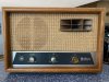
That said, I thought before I go poking around in something that actually works well and costs a good bit of money, I'd get something inexpensive and simple to work on. Enter the Hoffman ST-2 Amplified (Mono) Speaker, manufactured in Los Angeles circa the 60's? Here's a snippet from the Science Museum Group website about the company:

"H Leslie Hoffman bought the Los Angeles-based Mission Bell Radio Corporation in 1941, renaming it the Hoffman Electronics Corporation; manufactured radios, televisions, navigation equipment, radar and solar cells; parent company sold to Gould Electronics 1977; note Hoffman Video Systems founded 1978 and continue to date (2009) specialising audio-video systems integration."

After a visual inspection, I feel confident in saying all parts original (even the tubes). Applying voltage gently using a variac, the amp powers up and reproduces audio fed to its line input. Visual inspection of the output shows good square and sine waves, but playing regular music reveals weak performance at higher power levels. I tested the EL84 power tubes on a vacuum tube tester of unknown calibration and they FAIL emissions test. The tester seems to indicate properly on known good valves, so I think as a ballpark, I can trust that the EL84 valves need replacing and have some on order.

More importantly however, and possibly the reason why the EL84s have failed is the fact that this amp has two paper/wax coupling capacitors that I have not tested for leakage (parallel resistance, not ESR), but suspect they need replacing, and will replace whether they pass or fail any future test I may subject them to. Problem is, the caps are marked "1 MFD 600V" while the schematic (photo attached) shows them to be ".1MFD 600V." This is a discrepancy I do not know how to resolve. Does anything rule out one or the other value, or is the value in any audio amp for coupling caps dependent on the design of the particular circuit? I am not familiar with this particular circuit (or the intricacies of any circuit, really), so maybe someone who knows what the value for the capacitor for this high-pass filter in this example should be (might be) can shed some light on the problem for me.

Much appreciated. Enjoy the photos.
IMG_0670.jpeg tempImageEXzAr8.png IMG_0686.jpeg IMG_0688.jpeg IMG_0689.jpeg IMG_0690.jpeg IMG_0691.jpeg

IMG_0700.jpeg
IMG_0680.jpeg
 

Attachments

  • image.jpeg
    image.jpeg
    138.7 KB · Views: 2
Last edited:
Register to hide this ad
Looks like the same chassis my Hoffman console uses. Mine is an older two piece stereo, so each box has a mono integrated amp. I've got tone controls and an input selector switch along with a bigger output trafo but if thats not the same steel chassis I'd be absolutely amazed. Same basic schematic as mine now are since the tone controls have been bypassed. Originally mine had an EF86 input tube, but I triode-wired it so its not that different than a 6AV6 now.

The 1uf cap is the tweeter "crossover". Mine had that too originally. Pretty sure the coupling caps into the 6bq5 tubes are 0.1uf
 
Hi ToanDef, Welcome to AK ! :)

Now I'm not gonna state for 100% certainty, because it seems whenever I say "It's gotta be this way" , Someone ends up pointing out the one example I've never seen, but I've never seen a full one microfarad cap used as a coupling cap in any of the amplifiers I've worked on. I'm used to seeing values of .1 or even .01, and .05 used in that application, So hopefully someone here will know for certain.

Hi init4fun (thanks for the help and warm welcome) and gadget73 (thanks for your help). I hope you both don't mind if I consolidate my response . . .

Since posting my original question yesterday, I've been paying more attention to the coupling cap values in the various circuits I've come across (yes, I'm a circuit junky now), and I have to agree with the conclusion that 1.0.uF can't possibly be the value I was looking for, so I traced out the circuit again just now and confirmed that the two "1MFD" wax caps are indeed in the circuit location of the coupling caps. Scratching my head I thought, maybe the decimal (dot) is buried under the wax . . . so I scraped the wax off where the decimal point should be and lo and behold, there it was.
IMG_0711.jpeg

The two wax caps are indeed the coupling caps, each with a value of 0.1 MFD . . . and yes, as gadget73 claims, there is a separate 1.0 MFD cap (blue with yellow lettering, molded cap) that serves as the high-pass filter for the "tweeter." TOTAL NEWBIE FACE-PLANT! I've watched Mr. Carlson scrape so many of these wax caps, I should have known better than to not have done so in the first place.

Well, valuable lesson learned here for sure. At least we have some photos and a schematic to look at as well, and maybe some other newbie in the year 2047 will find this post and benefit from it.

In conclusion, I want to thank you both for your help.

Audiokarma.org is an amazing site with a treasure-trove of great information provided by a lot of really smart folks. I think it will be a great resource for all my future forays into the quirky and wonderful world of everything Audio!
 
It seems dumb and basic but I started comparing the physical size of caps to the others around it when the value was uncertain. Is the cap on question larger than or smaller than a .5, or .47 in the same amp?
How does it compare size wise to a .o47?

At the same voltage, larger valve caps are generally going to have larger cases. Line them up smallest to largest, and let the missing data fill in itself, like a sudoku puzzle.

A lot of life is very basic and I tend to overthink it, way more often than I should.
This is one of those cases. Glad you found your decimal point. You'd have figured it out one way or another.
 
It seems dumb and basic but I started comparing the physical size of caps to the others around it when the value was uncertain. Is the cap on question larger than or smaller than a .5, or .47 in the same amp?
How does it compare size wise to a .o47?

At the same voltage, larger valve caps are generally going to have larger cases. Line them up smallest to largest, and let the missing data fill in itself, like a sudoku puzzle.

A lot of life is very basic and I tend to overthink it, way more often than I should.
This is one of those cases. Glad you found your decimal point. You'd have figured it out one way or another.
That's a good technique. Problem in my case is that there were (and I have) no other capacitors that I could have used for the lineup.
 
That's a good technique. Problem in my case is that there were (and I have) no other capacitors that I could have used for the lineup.
This is your first rodeo. You'll have a heck of a stash of dead caps in a year or two.
I have a special waste basket named the "capacitor checker" if a cap makes a sound when it hits the bottom, it was definitely bad.

Every 5 years or so I put the collection on ebay, and collect a few Benjamin's from the guitar people. They're happy, I'm happy.
I take the money and buy new caps from Mouser.
 
didn't notice it previously but they actually put the volume control inside the feedback loop. Very strange place for it. Volume pot being direct coupled to the plate of the 6AV6 is also weird. Electrically it works because it "grounds" through the same cap that "grounds" the lower inverter grid, but again, weird.
 
Here's the Sams for the console version that uses the same amp. It's in pdf, which can be enlarged to view detail.
Oh wow, it looks almost identical, except for maybe the phono input and a few minor details. Chassis and tube complement, stupid "loudness" and tone controls the same, output seems a little different, but otherwise, very very similar. Nice catch!
 
didn't notice it previously but they actually put the volume control inside the feedback loop. Very strange place for it. Volume pot being direct coupled to the plate of the 6AV6 is also weird. Electrically it works because it "grounds" through the same cap that "grounds" the lower inverter grid, but again, weird.
That's all mumbo-jumbo to me at my current level of understanding, lol.
I've recapped all the electrolytic and the signal path caps, replaced almost all of the carbon comp resistors too . . . put in new power tubes and swapped in a used EH 12AX7 to replace the original Hoffman version (Made in Holland). Sounds a bit cleaner now, but not a drastic change . . . What I do notice is that despite my efforts to clean up the underside wiring with a focus on reducing hum, some hum still persists. Not sure how much hum is normal for amps of this level and vintage. Not sure how much of it is due to circuit design and the output transformer being a little weak looking. I wanted to get it to sound as good as my Jolida, but fat chance that's going to happen. I added a fused IEC power outlet as well. I think the next thing I might try is bypassing the tone and volume controls because the "loudness" feature really messes with the neutrality of the sound and it's active up until the volume dial is turned up to 95%.
 
Probably an Amperex tube. The two Hoffman branded Amperex 12AX7's from my amps were by far the noisiest 12ax7 tubes I have ever run across. No idea why, nothing about the amp abuses them and Amperex tubes are generally considered to be good quality but those specific two are junk.

Mismatched output tubes will cause hum. The supply isn't really well filtered, so it relies on equal current draw in the output stage to cancel out residual noise.


The volume control placement is just strange because of how negative feedback works. The purpose of feedback is to take some of the output signal and feed it back to the input. On this one specifically, the connection is from the speaker output to the cathode of the 6AV6 through R13 and C8. As that signal decreases, the gain of the amplifier increases to compensate, with the overall effect being that the output level of the amplifier remains pretty constant. Its used to level out frequency response and decrease distortion. With a control in the middle, what I would expect to happen is the feedback level would decrease along with the volume control setting so the frequency response at lower levels likely wouldn't be as flat, and distortion would be higher. Just from a measurement perspective, best performance is probably obtained with the volume control full up.

the direct coupled thing just means that the volume pot is tied direct to the plate of the 6av6. Its got 75 volts on it, which isn't typical for volume controls.

If you remove the volume control you will need to sub it with a fixed 1M resistor. Pin 2 grid ties to pin 7 of the 6AV6. 1M resistor from pin 2 to pin 7. 0.1uf cap from pin 7 to ground. C9, R14, C10 go away. Leave C7. If you just want to delete the loudness function, C9, R14, C10 can go and you'd have a standard volume control.

Losing the bass and treble controls may also get you some gains. If you do that, C6 connects directly to the input selector switch. It will end up louder since there isn't any loss from the tone controls. Can probably sort that with some resistors to drop the signal, but it likely would need a small value cap in the mix to keep it from rolling off the treble too much. That would need a little experimenting to arrive at the right value.
 
Probably an Amperex tube. The two Hoffman branded Amperex 12AX7's from my amps were by far the noisiest 12ax7 tubes I have ever run across. No idea why, nothing about the amp abuses them and Amperex tubes are generally considered to be good quality but those specific two are junk.

Mismatched output tubes will cause hum. The supply isn't really well filtered, so it relies on equal current draw in the output stage to cancel out residual noise.


The volume control placement is just strange because of how negative feedback works. The purpose of feedback is to take some of the output signal and feed it back to the input. On this one specifically, the connection is from the speaker output to the cathode of the 6AV6 through R13 and C8. As that signal decreases, the gain of the amplifier increases to compensate, with the overall effect being that the output level of the amplifier remains pretty constant. Its used to level out frequency response and decrease distortion. With a control in the middle, what I would expect to happen is the feedback level would decrease along with the volume control setting so the frequency response at lower levels likely wouldn't be as flat, and distortion would be higher. Just from a measurement perspective, best performance is probably obtained with the volume control full up.

the direct coupled thing just means that the volume pot is tied direct to the plate of the 6av6. Its got 75 volts on it, which isn't typical for volume controls.

If you remove the volume control you will need to sub it with a fixed 1M resistor. Pin 2 grid ties to pin 7 of the 6AV6. 1M resistor from pin 2 to pin 7. 0.1uf cap from pin 7 to ground. C9, R14, C10 go away. Leave C7. If you just want to delete the loudness function, C9, R14, C10 can go and you'd have a standard volume control.

Losing the bass and treble controls may also get you some gains. If you do that, C6 connects directly to the input selector switch. It will end up louder since there isn't any loss from the tone controls. Can probably sort that with some resistors to drop the signal, but it likely would need a small value cap in the mix to keep it from rolling off the treble too much. That would need a little experimenting to arrive at the right value.
Wow, super useful information, gadget73. You really seem confident about your design modification suggestions, and instill the confidence in me to attempt these modifications. Can you confirm that you are referring to the schematic I uploaded in the OP, just to be sure? Also, it seems some of the mods you are suggesting jump from the loudness pot coming into the ECC83, over to the plate side of the ECC83/EL84 junction of the schematic, and I don't understand the connection. I'll need to take a closer look at your instructions and see if it all makes sense to me, and see if I can pull it off without releasing the magic smoke . . . too many times. I also read on another post in these forums that one of the most critical components determining SQ in a tube amp is the output transformer. The one on this unit looks cheap as hell and built to a price. Do you think a "beefier" or higher-quality xfrmr could be readily purchased/found, and would it yield some improvements? I realize from a practical perspective, the time I am spending to optimize what is clearly a mono, limited amplifier is a fool's errand, but I'm not really trying to find audio nirvana. My aim is to learn as I go, and maybe see how good I can get this thing to sound with a few modern components and some reasonable design changes. . . and maybe get a little closer to understanding what makes one implementation/design (given the same hardware) sometimes substantially better than another. From my perspective, it's all just a bunch of tubes and passives and wires . . . those are the constants. Discounting the quality of those components between one amp and another, all that is left to make a difference is the implementation and design. I hope to learn something about all of it . . . I've been tearing apart perfectly good electronics since I was five years old in the Early Seventies (when tube gear was still in every household) to find out what makes it tick - always been fascinated by electronics, but never quite applied myself due to lack of a practical purpose, and other priorities in life. But now I have found the perfect marriage of audio and electronics, and the mental maturity to take on the challenge and couldn't be more excited to take on this wonderful new hobby.

Thank you for your sincere attention to my specific challenges. It is much-appreciated. BTW, I'm not implying that I expect any commitment from you by any means, but I've seen your posts elsewhere and judging from your messages count, I don't think you'd hesitate to be of great help. :)
 
part numbers are from the schematic that @FlaCharlie uploaded. Its easier for me to read the part numbers on that one since I can blow it up to a bigger size. Probably where some of the confusion comes from. The fixed resistor basically simulates the volume control at wide open. Removing the other parts is mostly because with a fixed resistor there isn't anywhere for them to attach anyway.

Different output transformer might improve the bottom end, but I'd try and squeak the most out of the stock parts as possible just because I'm cheap. Iron is expensive, passive bits aren't.

Another spot you might be able to get some gains out of, take a 47-100uf 50v or so capacitor and wire it across the 160 ohm cathode resistor. That should improve the bottom end somewhat, up to the limits of what the transformer can actually do.
 
In my humble opinion, I would leave the output transformer stock otherwise you have to start changing resistors and capacitors to get the feedback somewhat manageable.

Also, I would leave it all stock 'cause that is a nice cabinet and all.

When you say you replaced the capacitors, did you also replace the 4 inside the can capacitor? Doesn't matter tube or solid state, it should have no hum.

Matched output tubes would also help. :thumbsup:
 
In my humble opinion, I would leave the output transformer stock otherwise you have to start changing resistors and capacitors to get the feedback somewhat manageable.

Also, I would leave it all stock 'cause that is a nice cabinet and all.

When you say you replaced the capacitors, did you also replace the 4 inside the can capacitor? Doesn't matter tube or solid state, it should have no hum.

Matched output tubes would also help. :thumbsup:

I agree with you. I have no plans to change the output transformer. This is a $40 unit that I bought for learning, not for hifi listening, though it does sound very, very good. I did replace the old output tubes with a matched pair and also the pre-amp and rectifier tubes and changed out all the caps, including the ones in the can, with some mid-range components and installed carbon-film resistors which made a drastic improvement in the SQ and also greatly reduced the hiss/hum. I'm playing out through a low-end Polk speaker ATM, and the only thing holding this system back from sounding even better is the speaker and the fact that it is a single-channel system. Still, an amazing deal for the $100 or so I've put into it. I'm keeping a lookout for another unit to pair up with it for stereo sound. Will make for a nice "B" system.

Thanks to all, especially gadget73 for the great advice. I will update this post as I muster the courage and gain more knowledge to do so, but I'm happy with the sound for now and use the system more than my primary, so I don't want to break it just yet . . .
 
What size is the original speaker? There are some nice modern full range speakers that won't break the bank. Some with decent low end too. You probably wouldn't even need the tweeter hooked up. If it's 8", Radio Shack sold some nice full range speakers with a wizzer cone that sound very good. They pop up in bartertown and ebay new in the box all the time.
 
Back
Top Bottom