Wow didnt expect this response plus emails in this short of a time. Ok here goes and if I forget your question Im sure I will remember later and answer it.
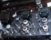
The idea of the 6146s came from the defunct AM exciter/modulator as it used them in the plate modulator circuit in a class-B configuration to get something on the order of 500 watts for a 100% modulation swing then off to the BIG tube and antenna. I dont remember the make but the small transformers were for audio distribution through the plant or station at 600 ohms and was also tapped for 8/32 ohms as well. The idea started brewing in my head early in the year to build an amp using transmitting tubes instead of expensive and tempermental 6L6s or EL34/6CA7s. The 6146s can handle almost 1/4 amp of current across the plate and not melt down plus they are much better matched seeing they are expected to run as RF finals to 175 MHz and not drift around while in mobile use. The only downside was drive, the 6146 wants alot of drive across the grid while they run in the linear regions of their curves so the swing is actually measured in milliwatts while running class-A or AB1, class-B the grid drive positive is measured in watts with a fixed reference resistor. AM exciters were all business.
The paraphase section was a cleaned up version used by Harris but turned on its head for class-AB operation and eliminated the need for the extensive amplified feedback/detector circuits and the net result was a low-gain pentode/triode phase splitter with a tuned cathode feedback circuit that takes almost an hour to properly tune. The 6GH8A I believe is also used in several hifi amps like Dynacos so they have been proven in this application. I gave thought to the use of the 7199 however its expense and availability is a limiting factor, I literally have over 1500 6GH8A tubes to choose from having stripped many RCA CTC series TV chassis. The drawback to the 6GH8 is the microphonics and heater hum when used in a high gain stage or elevated cathode on the pentode side.
The driver section is a conventional resistance coupled amplifier that was fine tuned through the use of a nailboard and recycled pots to set the resistance and gains for the lowest distortions and best gains. I used my motorola communications monitor for signals and specrum analysis and found the stage itself to be pretty flat from DC to 45 MHz only showing spikes from inter-element resonances outside of my hearing range, Im sure my kid can hear them but he thinks Im nuts anyway. I cap coupled directly to the 6146s through a conventional center fed grid resistor arrangement for an effective impedance of 50K ohms, anything higher tended to bring the noise floor up along with the gain but also lost bias stability and channel isolation. I run -60 volts on G1 for bias and swing the grids up 25 volts for full power, the transformers really hate me for this however but I hardly run the amp past 10 watts anyway. When I do drive it hard the transformers hit their limits of saturation and begin to produce a mellow crunch, Im sure if the core was thicker the useful output could be extended another 3-4 db but driving a set of Polk bookshelf speakers the power isnt needed.
plate caps? who needs them! I dont have a cat anymore, the last one expired on his own after 19 years of chasing yarn, birds and anything else that moved. He was a good friend to the end but a tad arrogant and high strung. My kid knows enough not to touch a plate cap having learned this at an early age. I didnt get after him for his use of colorful words, the lession was more important!
How did I keep the cost down? Well thats a hard one to explain. I guess its just look at the parts for what they are capable of doing and not really cared what the former application was. High voltage transformers were common in older TV sets along with base station communications radios and very good audio transformers were used during the heydays of AM radio where they were expected to work hard for decades on end. To answer the email I received I dont remember the exact model of the exciter but it was part of a transmitter house for a small town AM station that went to a syndicated oldies format and dropped its power down to 250 watts daytime only! A solid state transmitter was put in its place that was no bigger than a cube filing cabinet and weighed about as much with the supply. They also lost that nice sound punch through the use of bandpass limitations. 3.0 KHz is the absolute limit at 100% carrier modulation and the low shelf is 300hz... just like a telephone 16H44 circuit. The tube sockets were liberated from a dead Tek-545 scope along with many of the pots and precision resistors that I recycled. I even made use of the time delay tube using it to control the 5U4 rectifier heater, once bias is established the time delay heats up and 30 seconds later turns on the 5U4. If bias is lost it cools down and kills the supply faster than it heats, turn around time is 5 seconds and the 6146 is designed to operate at 100% plate current making it glow right to the edges.
The chassis was a surplus Bud box I picked up with a twin however ended up mutulating the twin while drilling the pilot holes for the tube sockets. I punched them with greenlee punches in the end however having to drill mild steel with a 3/8 bit and little to support everything got loose. I tried to save time by drilling a single rather than step progression. Oh well.
ok whos question did I forget?
109





 Seriously though, that is a very cool amp. I've thought about 6GH8As. Seem to be plentiful and affordable. 50 Bux? :thmbsp:


