• The move to the new server is done. There are some software and database maintenance updates in process. This has us passing the hat around to help out. We appreciate any donations. Seriously, even a dollar helps. The payment page may be found here - https://www.audiokarma.org/support.html

How much ripple is too much ripple?

View attachment 2810438

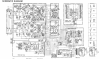
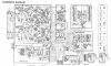
View attachment 2810438 So there's the schematic. Any interest in helping a marginally skilled, semi-equipped, eager to learn guy track this problem? In case that upload can't be read here is a link to the manual download. https://www.hifiengine.com/manual_library/nikko/alpha-450.shtml
You may want to check your rectifier(s), should be in a bridge configuration, whether using 4 individual diodes or the single block type with 2 leads for AC in, plus the positive & negative output leads out. May have a fault in there, just speculating since I've no pics of the unit in question, & the schematic posted off hifi engine blurs up when enhanced to the point I can barely make out maybe 10% of it.
 
Too much Ripple is when the 1st bottle goes tits-up & the search commences for bottle no.2. Once no.2 is opened, that may be "too much ripple!":yikes:
 
You may want to check your rectifier(s), should be in a bridge configuration, whether using 4 individual diodes or the single block type with 2 leads for AC in, plus the positive & negative output leads out. May have a fault in there, just speculating since I've no pics of the unit in question, & the schematic posted off hifi engine blurs up when enhanced to the point I can barely make out maybe 10% of it.
I tried again, can mostly make out discrete diodes on regulator board. Look there. An oscilloscope would help here.
 
Typically a 120 Hz hum is due to a bad filter cap not smoothing out the "humps" from the rectifier. 60 Hz hum from the PS is typically a bad diode in the rectifers so there is no inverted negative side of the 60 Hz wave. The filter caps won't be able to smooth that very well.

Bad grounds will do the same thing. An oscilloscope will tell you if you can get your hands on one, Better than shot-gunning parts, although if one filter cap was leaking I'd condemn all of them, the rest aren't going to be in better shape. And that, in my experience, means every electrolytic cap in the unit is questionable. If someone drove that amp hard enough to overheat the main filter caps, none of the rest have escaped without damage.

 
I tried again, can mostly make out discrete diodes on regulator board. Look there. An oscilloscope would help here.

I have a scope and basic knowledge on how to use it. I have made another discovery this morning. This unit has +- 73v rails and +- 77v rails. The 73v pair seem fine but the 77v pair are only at about 71v. I assume this is a problem I'm just not certain of the troubleshooting method.
 
Typically a 120 Hz hum is due to a bad filter cap not smoothing out the "humps" from the rectifier. 60 Hz hum from the PS is typically a bad diode in the rectifers so there is no inverted negative side of the 60 Hz wave. The filter caps won't be able to smooth that very well.

Bad grounds will do the same thing. An oscilloscope will tell you if you can get your hands on one, Better than shot-gunning parts, although if one filter cap was leaking I'd condemn all of them, the rest aren't going to be in better shape. And that, in my experience, means every electrolytic cap in the unit is questionable. If someone drove that amp hard enough to overheat the main filter caps, none of the rest have escaped without damage.

The entire unit has been re-capped. One of the main filter caps had leaked and corroded the area where it was mounted so I ultimately just re-capped the whole thing. Unfortunately re-capping didn't help with the noise problem. I have also reflowed everything in case a bad joint was my problem, nada. I do have a scope and very basic knowledge of how to use it, I just need a little troubleshooting guidance from someone with more experience than me.
 
Downloaded the service manual.

Take a look at the grounds on the main amp board, all the PS circuits ground there and an iffy ground from corrosion or cracked solder will render the filter caps ineffective. If the board ground through solder pads and screws, check to make sure the solder isn't badly oxidized.
I would also verify that the copper traces around that leaking cap aren't compromised, it's possible for the to be corroded and cracked under the green resist coating, or fractured at the solder line at the pad.

Check all the rails for ripple, I'm not seeing any pass transistors to remove ripple.

Low voltage on one of the channels (two separate rectifiers) could be a faulty diode in the rectifier.
 
Downloaded the service manual.

Take a look at the grounds on the main amp board, all the PS circuits ground there and an iffy ground from corrosion or cracked solder will render the filter caps ineffective. If the board ground through solder pads and screws, check to make sure the solder isn't badly oxidized.
I would also verify that the copper traces around that leaking cap aren't compromised, it's possible for the to be corroded and cracked under the green resist coating, or fractured at the solder line at the pad.

Check all the rails for ripple, I'm not seeing any pass transistors to remove ripple.

Low voltage on one of the channels (two separate rectifiers) could be a faulty diode in the rectifier.

Thank you! Will check all of this. As a side note, while working this morning I also discovered that the +-77v rails read about 71v, another clue perhaps?
 
Maybe, would make me think a rectifier problem if one channel is 77 and the other is 71. If both channels are the same I don't think that's the issue.

The schematic I have indicates only a +-77 rail for each channel with a separate rectifier and filter caps. There is smaller PS rectifier with 1000uF caps that powers the A/AB switching board, not sure of the voltage on it.
 
Maybe, would make me think a rectifier problem if one channel is 77 and the other is 71. If both channels are the same I don't think that's the issue.

The schematic I have indicates only a +-77 rail for each channel with a separate rectifier and filter caps. There is smaller PS rectifier with 1000uF caps that powers the A/AB switching board, not sure of the voltage on it.

Ok, let me work on things and I'll update. Thank you!
 
Downloaded the service manual.

Take a look at the grounds on the main amp board, all the PS circuits ground there and an iffy ground from corrosion or cracked solder will render the filter caps ineffective. If the board ground through solder pads and screws, check to make sure the solder isn't badly oxidized.
I would also verify that the copper traces around that leaking cap aren't compromised, it's possible for the to be corroded and cracked under the green resist coating, or fractured at the solder line at the pad.

Check all the rails for ripple, I'm not seeing any pass transistors to remove ripple.

Low voltage on one of the channels (two separate rectifiers) could be a faulty diode in the rectifier.

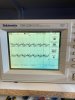
Examined the grounding point, looks great, no oxidation, all solder good. Went over the copper traces around the formerly bad cap all looks good and there is continuity where it should be. I've included two pics of ripple measurements. the first is the + and - 73v lines, it's quite high. The second is the + and - 77v lines, those look a little more in line. Ignore the single horizontal and vertical lines through my oscope display, its a problem I've had with my scope that haven't had a chance to look into.

+- 73v.jpeg +-77v.jpeg
 
I see three main power supply circuits on the schematic, a 77V for right channel, a 77V for the left channel, and a third one of unknown voltage (not marked on the schematic) for the A/AB regulator board. Left channel is on the small regulator board with the supply for the switching regulator, right channel is on the switching regulator board.

The spikes on the 77V rails make me think diode problems in the rectifier, but I have no direct experience to make that determination. If the noise is in both channels I'm stumped.
 
I see three main power supply circuits on the schematic, a 77V for right channel, a 77V for the left channel, and a third one of unknown voltage (not marked on the schematic) for the A/AB regulator board. Left channel is on the small regulator board with the supply for the switching regulator, right channel is on the switching regulator board.

The spikes on the 77V rails make me think diode problems in the rectifier, but I have no direct experience to make that determination. If the noise is in both channels I'm stumped.

Ok thanks. You actually pointed out something I failed to originally recognize, the 77v is supplied separately for each channel, I wrongly assumed it was the same supply for both channels, should’ve followed things back further. The 73v I’m referring to is labeled in the lower left section of the schematic running between the right channel circuitry and the protection circuitry. I’m shutting it down for the night and will revisit later in the week. Thank you very much for your help!
 
Working on an amp that is noisy (110hz hum) and I’m measuring 250-300mV of ac ripple when cold dropping back to about 200mV when warm, off the power supply. I thinking this is too much and likely the source of my noise. Am I on the right track here or totally wrong?

Should be less than 20mVAC. I experimented with several PSU's for my phono pre-amp. Hospital Grade Meanwell measured 5mVAC and made the pre-amp dead quiet.

As for Ripple... I prefer Mad Dog 20/20! A real man's drink!

Mad Dog 20-20.jpg
 
ripple in a phono preamp, particularly something that isn't a split rail design and ripple in the output stage of a power amp are very different things.
 
Back
Top Bottom