• The move to the new server is done. There are some software and database maintenance updates in process. This has us passing the hat around to help out. We appreciate any donations. Seriously, even a dollar helps. The payment page may be found here - https://www.audiokarma.org/support.html

How to increase power (MCS 3235 to 3245)

Racingh11

Super Member
I recently modified an MCS 3245 receiver to greater power output using a 3275 transformer and other modifications. It can be read in this thread: https://audiokarma.org/forums/index.php?threads/how-to-increase-power-mcs-3245-to-3275.968122/

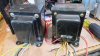
The second conversion I did in that thread left me with a good 3245-10 transformer. So now, I'm installing that in an MCS 3235 receiver and making necessary changes.

This build will require all new power-amp transistors, due to voltage requirements. The transformer is the same physical size as well as the rectifier diodes. Should make it easy. Fuse amperage will be increased. And a temperature controlled cooling fan will also be installed.

It is also getting a complete electrolytic capacitor replacement and larger power caps.

Pictures and details coming soon.
 
Register to hide this ad
I started on this project. Replaced caps and transistors, except the MJ15016s that aren't available. I ordered some from digikey that were NTE brand. What I got is pictured below. They came direct ship from NTE, so I thought they might be good. I was wrong. Testing the original 2n3055s, 2n2955s, and new OnSemi Mj15015s; and the gain was about 260 for all. Testing the the ones from NTE, turned out a gain of about 26-28 on either MJ15015 or MJ15016. So, I can't use them for this project and expect good results. Low performance and burned drivers would be the result. I will have to wait a couple of months unless a pair come up before then...

IMG_0182.JPG
 
Last edited:
I got all the transistors in, and then the low filter switch broke inside. So I found a preamp/tone board for sale and got the switch from that. The receiver is now idling fine on the original transformer. The problem now is the 3245-10 transformer doesn't have a 24VAC winding to use for the regulated voltage supply. The two ways I'm thinking of at the moment would be to use the high voltage source and regulate it through a resistor into a zener diode and capacitor like the 3245 does. Or I'm wondering if a voltage multiplier would work in the circuit and use the 17V or 11V winding. I measured all the resistors fed from that 24V regulator and it uses about 120mA at idle.

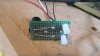
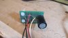
I also got the cooling fan rectifier board done and mounted under the chassis.
IMG_0447.JPG IMG_0446.JPG
 
Last edited:
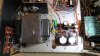
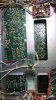
Driver board with all new transistors to meet specs and new electrolytic capacitors. The heatsink will get more mass/fins added on to it and a cooling fan on top of that.

IMG_0448.JPG
 
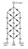
For the voltage multiplier, I should be able to modify the original 3235 rectifier circuit for the 24V regulation. Basically I would be turning it into the second stage of this circuit. Just need a couple of capacitors and cut a couple of traces on the board. And may need to build the first stage on a separate board. Or maybe make it a half-wave multiplier single stage with only what's on the board.
Full wave Cockcroft Walton Voltage multiplier.jpg
 
Last edited:
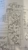
I worked on it more today. It went well. I managed to make the half-wave single stage voltage multiplier on the board. I removed diodes D602,603, capacitors C602,603 , and added an input charging cap, and a jumper where D603 was. It doesn't show which position they are in the schematic, but the schematic also has errors on the polarity of the D601-604 rectifier diodes, and also C614. The voltage was 32.4VDC before regulation and 22.6VDC after with the factory transformer and power board. It also had .428mV peak to peak ripple in the unregulated cap, and 70mV ripple in the regulated cap. After I added a 220uF charging cap and used the factory C605 470uF for the unregulated. It put out 32vDC. Even though it was close to original measured voltage of 32.4V, the service manual shows 34V. So I added another 220uF in parallel to the other charging cap and got 34.35VDC. I added it because I don't have any bipolar caps of larger capacitance. This had 2.16V peak to peak ripple on C605 and 72mA on C607. I changed the stock C605 to 1000uF and the ripple reduced to 1.2V peak to peak and raised the charged voltage to 34.76DCV. The regulated C607 side remains about the same. I will order a 470uF bipolar cap for where I had the pair of 220s. I just haven't decided if I will just put it in between the transformer wire and the pin it goes to, or open the trace from below and mount it out of sight. So far everything is easily reversible, so I may leave the board alone and mount on the topside. What I did was get the stock 34VDC from the 3245-10 transformer 17VAC winding. It would have got close to the 24VDC needed, but not high enough for good quiet regulation. The power rail voltage with the new transformer is +/-44.9VDC, stock being 38.8V.
IMG_0461.JPG
The added input cap for the voltage multiplier is the green one on the corner of the power board, and glued down with strong adhesive.
IMG_0470.JPG
 

Attachments

  • IMG_0471.JPG
    IMG_0471.JPG
    101.7 KB · Views: 15
Last edited:
I installed the new 470uF capacitor and the unregulated voltage went to 36.4V. I must have had some resistance in my test leads when I was trying those caps. I then reinstalled the 220uF on the board and got 33V compared to factory measured 32.4V at C605. And got 23.6V on the regulated output. Then I distortion tested it. .023 and .026% THD at 50W and a couple thousandths less at 35W, This is right on spec from other stock units I tested. .013 and.014% at 10W. All at 8 ohm with both channels driven. Bias current setting did not have an effect on distortion even at low voltage 20khz, so I set it to the stock 6.6mV spec. 1% THD clipping was tested and was 67W - 8 ohm and 90W - 4 ohm. Pretty good for a "35 watt" receiver rated at .3% THD! Damping factor is 100. It idles at 15W line power without the light bar and LED. DC offset measured 1.3 and 3.4mV. Next I will be mounting the heat-sink addition and cooling fan. I will add photos soon.
 
Last edited:
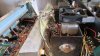
I mounted an additional heatsink to the original one using a pair of 10-32 screws and some thermal compound. I then mounted the fan to the heatsink. This created a clearance issue with the cover. I then mounted a smaller fan to the heasink and it sounded like a siren. So I made a couple of brackets and mounted the first fan to the back panel and got it inline with the heat vent and proper clearance. The fan got wired to the rectifier board I made, and in series with a normally open 55C switch mounted at the center of the heatsink. I tested the system by blowing a hot-air-soldering-iron at the thermal switch until it activated. What's not shown in the photos is a large factory hole that is stamped in the chassis under the driver board for air flow from below, it should flow well.
IMG_0477.JPG

IMG_0488.JPG

IMG_0486.JPG
 
Last edited:
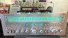
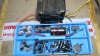
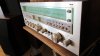
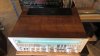
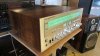
I got the tuner lens polished up and the face cleaned and installed. Then hooked it up on the test stand. Sounds great. I was able to get the fan to switch on when playing two sets of 8 ohm speakers. The temp stayed below 140F in 4 ohm, and the fan won't turn on with only 8 ohm loads. It got around 115F playing hard in 8 ohm. I also aligned the tuner before I hooked it up. The only thing remaining is the cover. I repainted the heat vent, and have the wood cover glued and clamped right now. It was coming apart at the front corners and will be as good as new when done. Here are some pics hooked up to the system and all the parts that were removed and replaced for service.
IMG_0494.JPG IMG_0491.JPG IMG_0492.JPG
 
Maybe one day I might be able to delve into repairs though just into the basics currently. I have more than a few vintage components, including a nice hefty NEC AUA 8300E amplifier that sounds very good so not in a hurry to touch it though the thought that it could offer better performance if one at least did a cap replacement is tempting. Excellent work by the way.
 
When I started, I had some basics, then bought a bunch of old stereo repair books. They were interesting, every book had something different in it. I also spent a lot of time studying schematics from different brands.

I have had two or three MCS 3865 integrated amplifiers, which are an NEC AUA-8000. But never had an AUA-8300E. Make sure to post your work if you work on that one.

And thanks for the compliment.
 
Last edited:
It will hit a little harder on the bottom end and have a richer sound. At least that is how it worked when he did my MCS 3245 to 3275 xfmr conversion.

It's like a hot rod car, every single little horsepower that you can eak out of an engine counts.
 
I would also like to point out that this has more power than a stock 3245, so it is more than a 10W increase. And it runs cooler than a stock 3235, so it will live a long time.
 
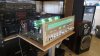
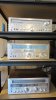
Nice stack of MCS. There is also a 3835 to the right of view. The 3245 at the bottom is the first one that was modified for higher power. The 3233 at the top is serviced with new caps.

IMG_0543.JPG
 
Back
Top Bottom