• The move to the new server is done. There are some software and database maintenance updates in process. This has us passing the hat around to help out. We appreciate any donations. Seriously, even a dollar helps. The payment page may be found here - https://www.audiokarma.org/support.html

how to reduce DC offset on 600-T

rickl

I'm just a bass player
Subscriber
I have an old 600-T (SN 26346F, hidden door, ...) that I'm trying to get working for a friend.

I replaced some caps on the high level amp board P1096.
I replaced the 1000uF caps (c34,c35) and 220uF caps (c32,c33) on the primary side of the interstage transformers.

I can inject a sine wave on AUX lo and get about 46Vpp on an 8R speaker load. This seems like plenty of gain.
600t-full-sine.jpg
DC Offset (no signal, 8 ohm load)
Right channel: 445mV
Left channel: 170mV

I have not adjusted the bias (not really sure how to do that).

Can I adjust the bias to help reduce the DC offset?

no diff pairs like more modern line stage boards.

here is the line stage
upload_2022-12-14_9-53-10.png

voltages seem ok at the output to the drivers.
2k: L -20.13V, R -19.75V

I had it on a DBT but these voltages are at house voltage (120Vac).

Any ideas? I have a scope, function generator, a few DVMs.
Thanks in advance!
 
Register to hide this ad
Aren't these cap coupled? If so there is no offset. Any dc at the output is caused by a leaky output cap.
 
here is some additional pics and info. I'm kind of embarrassed that i've ignored this for so long so I'd like to get it off my plate.

in post #3, Fred says Balance between these pots also controls output DC offset.
 
Last edited:
ok, not cap coupled. Disregard then.

yeah twin bias adjust like that would also shift the offset. Have to dial it in on each side of the output stage.
 
ok, not cap coupled. Disregard then.

yeah twin bias adjust like that would also shift the offset. Have to dial it in on each side of the output stage.

that is what I thought. I just don't know what to measure when adjusting the bias pot.

do I dial the base of Q6 to the schematic? get both sides the same? dial DC offset to 10mV (or so) on both sides?

Q6 base to pot to 2.7vdc?

upload_2022-12-14_13-4-46.png

I'm using this service manual
http://www.fisherconsoles.com/non console manuals/fisher 600t 21000 27000 sm.pdf

thanks gadget for helping. I've always appreciated your posts.
 
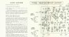
It's in the manual. About the 4th page in. You'll need an IM Distortion analyzer. Output's are germanium, and the pots are twitchy as hell. You can very easily blow the outputs if you hiccup at the wrong time. USE TWO TWEAKERS at the same time.
ScreenHunter 681.jpg
 
It's in the manual. About the 4th page in. You'll need an IM Distortion analyzer. Output's are germanium, and the pots are twitchy as hell. You can very easily blow the outputs if you hiccup at the wrong time. USE TWO TWEAKERS at the same time.
View attachment 2739904

Thanks Larry. I read that but don't have (or know how to use) an IM distortion analyzer. I haven't touched the pots for this exact fear. Plus, "step 3 - Turn to max volume" is worries me.

I can ask the neighbors if anyone has an IM distortion analyzer (you would be surprised what I can find in the hood) but I'm not hopeful. One guy has a full rack of test equipment but he is a guitar amp tech so he just uses his finger on an input cord. if the amp makes a hum from the cab, it works!

Would this work?
  1. warm up amp
  2. measure 5.16vpp on load with scope
  3. tweak both pots for 0vdc across load with two DVMs (one for each channel).
I always forget if 5.16vac is RMS voltage or peak to peak so this might not be right.

thanks again for your quick response.
 
Lets get @fred soop on this. He's the acknowedged master on the 600-T.

IIRC in Aux without a source connected, the unit should be dead quiet. It's not a worry because you're not introducing a signal.
 
First, take proper precautions before adjusting those original pots. As Larry said, you can blow the whole thing up if the wiper loses contact.

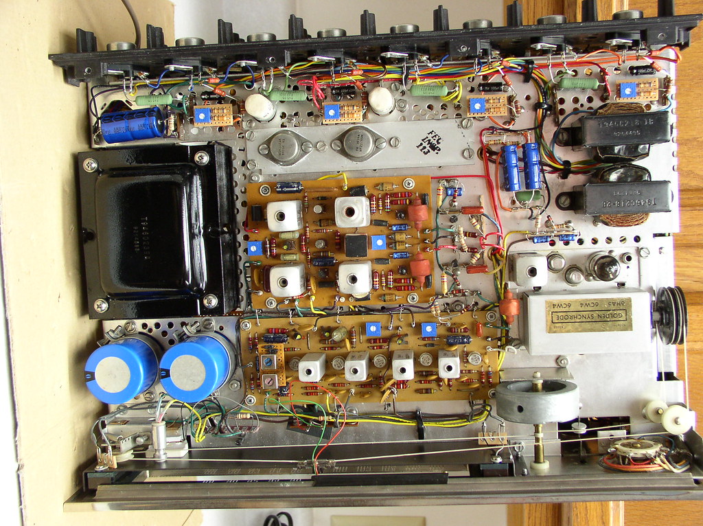
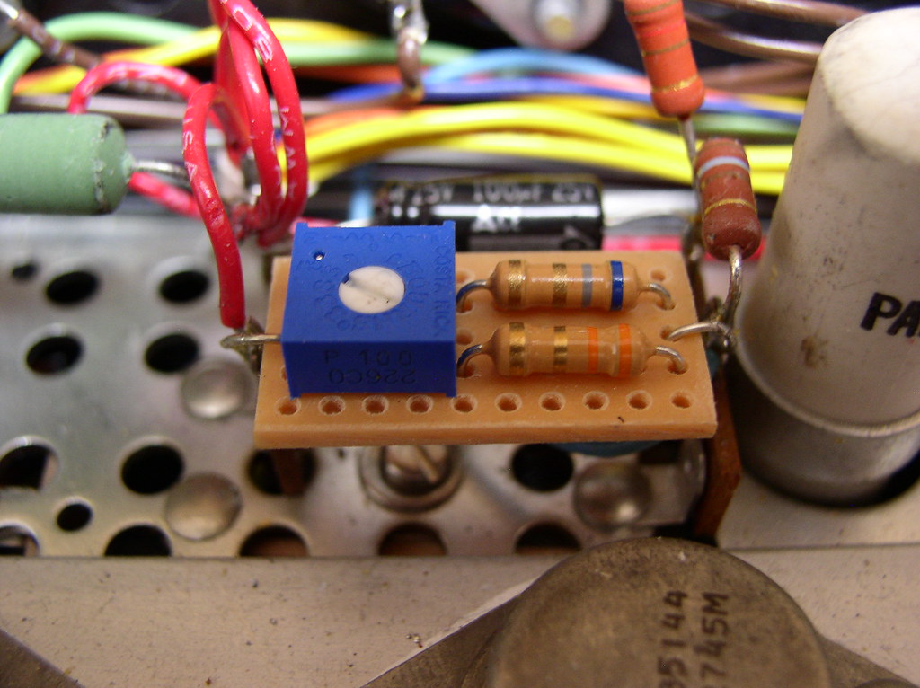
As you will note in post 3, my modification shows new Bourns bias pots (very reliable) with a series and parallel resistor that "traps" the resistance so the bias can be adjusted roughly between 1/2 and double what is needed.

Bias adjustments shown here .....
1407
12421427704_56a70725e0_b.jpg


If you do not modify the bias circuit, turn off power. Mark the bias pots for present adjusted position. Then measure resistance, preferably with an analog meter. Turn the pots end to end slowly, looking for any hiccups in the meter reading. Clean the pots repeatedly until the resistance change is smooth.

The Fisher procedure calls for an IM distortion analyzer, something that we all have right next to the basic voltmeter. Yeah, right. Adjust the pots to the previously marked position. Power up. Adjust for approximately 30 mV across the emitter resistors. (Note that my modification uses lower value emitter resistors and 10 mV would be approximately 30 mA.) The adjustment within each channel are somewhat interactive, so repeat the adjustments until there is no further change in bias.

DO NOT use that 2.7 volt number shown in the box. Any voltage numbers in any of those boxes are signal levels for maximum output power.

After adjusting for 30 mV, if there is output voltage offset, make a slight adjustment in one or both pots to balance it.

Note: Nothing in the preamp or driver sections has any effect on any DC voltage in the output stage because the driver transformer isolates it.
 
Thanks Fred. I knew there was something about Voodoo and tossing broken chicken bones and fuzzy dice in the air WRT the 600-T. :rolleyes::biggrin:
 
Series 6? I have a 5 and a couple of 7's. I know people tend to look at analog meters as obsolete garbage but they're still very useful. That 'output' function is pretty handy. Its got a DC blocking cap, so you can measure AC riding on top of DC. Good for doing stuff like measuring audio signal at a tube plate, or ripple in a power supply. I've even used it to measure AC on a car charging system to confirm problems with the alternator.
 
i've decided to rebuild the bias per Fred's updates.
  1. The 260 doesn't seem to work as well as I'd hoped but I'll get that working too. it does come with the original case. last calibration in 1985.
  2. The bias pots measure all over the place even after removing the leads to the existing bias components.
  3. marking and cleaning them didn't seem to do a lot.
  4. I really don't want to blow the germanium outputs
here are the parts i'm planning to order from Digikey
4 - PPC3.3BCT-ND, RES 3.3 OHM 1/2W 5% AXIAL
4 - PPC6.8BCT-ND, RES 6.8 OHM 1/2W 5% AXIAL
4 - YAG1219CT-ND, RES 0.33 OHM 5% 5W AXIAL
4 - 3386P-1-100LF-ND, TRIMMER 10 OHM 0.5W PC PIN TOP

I was thinking of getting this 25 turn trimmer but the 1 turn must work.
3296Y-100LF-ND, TRIMMER 10 OHM 0.5W PC PIN TOP

I hope @fred soop logs in tonight to verify. I really need to get these ordered and get the receiver done.

thanks everyone. I'll post an update once i get the parts and bias circuit installed.
 
The single turn pot will be ok. Bias and balance are going to vary slightly over time anyway and bias is not extremely critical.

After doing the circuit modifications, be advised that since the power amplifier section is isolated by the driver transformer, you can disconnect the ±36 volt supplies and run the power amp from an external supply as low as ±5 volts for testing. Set bias at the middle of the range. It will need to be set again when full voltage is applied. Obviously, power output will be quite limited but the low voltage is less likely to cause any damage if there are errors.

Closer view of the bias circuit ......

1424
12421163905_a6739a8846_b.jpg
 
just a quick update.

I built Fred's bias circuit and added the .33R emitter resistors and was able to dial the bias to 10mV across the emitter resistors and DC offset down to near zero V.

Then I injected a sine wave and the output looks good.

it is a busy time now but I hope to connect a music player and speakers to see how it sounds. Maybe Monday.

Thanks Fred! Your circuit worked great.
 
I finally got the receiver off DBT and started listening to it. Sounds really nice.

Bias and DC offset doesn't drift but very easy to update pre Fred's bias circuit.

Thanks again to all that helped!
 
Back
Top Bottom