• The move to the new server is done. There are some software and database maintenance updates in process. This has us passing the hat around to help out. We appreciate any donations. Seriously, even a dollar helps. The payment page may be found here - https://www.audiokarma.org/support.html

How to Wire 4 Pole Capacitor in 2230?

stahlhart

Active Member
After a lengthy absence, going through some of the recapping threads here -- apparently the interest in these four pole electrolytic capacitors happened after I last worked on my 2230. I had planned to go through and make a few changes -- mostly some more film caps for coupling in place of low value electrolytics, some more Silmic IIs in the power supply -- but I was also interested in trying out one of the four poles. It looks as though the Jensens are unobtanium now, so I'll probably have to go with Mundorf.

But I did some searching here and elsewhere online, and I'm not having much luck finding a clear diagram for installing one in a simple full wave bridge circuit -- i've seen photos and text descriptions, but I'd rather work from a diagram.

Here is the stock filter capacitor wiring:
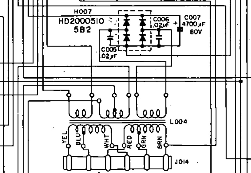
2230-psucap.jpg


I took a guess at how I thought it might be wired in after reading some about how they operate, but I'm still unsure, and not comfortable guessing about things like this:
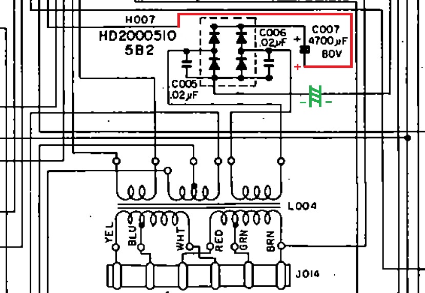
2230-psucap-4pole.jpg


Could someone who has done this (@patfont ?) critique/assist?
 
Register to hide this ad
Second question: the filter currently in place is a Panasonic snap-in, 6800uF -- should I stay at this capacitance value, or is there anything to be gained by increasing it to 10,000uF?
 
c007 is the filter capacitor .for it to do its job it has to be wired the same as the original diagram .
putting a capacitor inline with the ground will only cause problems . well i can't see it having a good outcome .
 
ok, + in would be from bridge, + out goes to the amp boards.
Going from memory there are 3 (red/or/orange) wires going to the stock cap Pos side, so the one from the bridge goes to Pos In, the two others (one for each amp board) go to Pos Out.

Hope this helps!
 
Thank you so much for the prompt, detailed response -- the runs that were intimidating me the most were for the ground side, but I'm assuming now that these also follow an in/out flow from the bridge as well.

Don't know about anyone else, but I really had to force myself out of the comfort zone, after so many years of old school electrolytics. Was just having some trouble visualizing the whole concept.

I'm not even sure yet that there are standard schematic representations for these components, because every diagram I ran across in my search was a drawing, and not a circuit diagram. Closest I got was this:

http://www.supertech-elec.com.tw/electronic/ECAPS/DMN_design.htm

Thanks again! :)
 
must admit its the first time I have seen those capacitors

Only about a week ago for me as well -- although I read in my travels in researching this further that Sprague apparently made a similar type of film capacitor many years ago, which I have zero recollection of. That jogged an old memory of a chassis component in a television set that you were not allowed to substitute, but it's probably completely unrelated to that.
 
Back
Top Bottom