• The move to the new server is done. There are some software and database maintenance updates in process. This has us passing the hat around to help out. We appreciate any donations. Seriously, even a dollar helps. The payment page may be found here - https://www.audiokarma.org/support.html

How to wire a volume pot as variable resistor?

vinyldavid

Collectorius Giganticus
Subscriber
How do I wire a mono volume pot from a cheap radio as a variable resistor for a DC motor?

There are 2 large tabs on the outer edge of the base, which are connected together (turning the pot has no effect on them), and then there are 3 pins on the bottom of it.....none of those do anything when I connect the motor wire.

I have the power supply + wire connected to one of the large tabs, and I have tried every single possible connection that I know of....

....is there anything that I am missing?

or can this even be done?

BTW, this is for my DIY turntable. I don't have a spare stereo amp to drive the Dual motor I was going to use, so I am using a small DC motor out of a Marantz belt drive turntable. The power supply is 19V, the motor is 12V. The motor runs. I just need to get control over it so that I can use it to drive my platter.
 
Register to hide this ad
Most volume-type pots aren't designed to have much current flowing through them and are rated at perhaps 1/2W or maybe 1W.

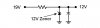
You need a better method of dropping the voltage to the motor. A simple zener voltage regulator will do the job, but you need to know first how much current the motor requires. The regulator shown below is good for small currents only (100mA max, preferably a lot less).
 

Attachments

  • simple_regulator.jpg
    simple_regulator.jpg
    14.4 KB · Views: 31
A pot would either fry, or have too much resistance for an adequate current flow.

You will need to make a variable power supply, or buy a cheap kit.

The first thing is to find out how much current the motor wants to draw.

here is a nice one for about 18 bucks using proven and reliable technology:
http://www.electronickits.com/kit/complete/powe/ck402.htm

the advantage to the kit is a proven printed circuit board, you don't want to spend a lot of time on the power supply.

The other gotcha may be the speed stability, and you may want to investigate feedback for speed control... what did the marantz used to use?
 
Most volume-type pots aren't designed to have much current flowing through them and are rated at perhaps 1/2W or maybe 1W.

You need a better method of dropping the voltage to the motor. A simple zener voltage regulator will do the job, but you need to know first how much current the motor requires. The regulator shown below is good for small currents only (100mA max, preferably a lot less).

Oh, Umm...I have no idea.

The other gotcha may be the speed stability, and you may want to investigate feedback for speed control... what did the marantz used to use?

The Marantz had a PCB with some transistors on it....with 5 wires that go to a button that changes the speed from 33 to 45. The motor connected to the board with a simple plug-in connector, and I clipped the wires on that far enough up that my clumsy hands can re-solder it. :yes:
 
I'm familiar with industrial DC motor control. These are pretty accurate and cheap, compared to other drives. It is probably overkill, but fun to play with:

http://www.grainger.com/Grainger/items/2M510

It would take some understanding of the 5 wires that you have exposed. Two are probably for the field windings of the motor, two for the armature and hopefully the 5th is for feedback. I assume that it probably is, considering that the turntable's accuracy will probably depend on closed loop control in the original design.

Your motor could also be permanent magnet for the field. Those, I am not as familiar with. This is probably not a practical solution, but the main point is that good DC motor control, while relatively simple, is more complex than a resistor (actually, a power rheostat). You might look for a hobby kit, depending on your electronics skills.
 
I'm familiar with industrial DC motor control. These are pretty accurate and cheap, compared to other drives. It is probably overkill, but fun to play with:

http://www.grainger.com/Grainger/items/2M510

It would take some understanding of the 5 wires that you have exposed. Two are probably for the field windings of the motor, two for the armature and hopefully the 5th is for feedback. I assume that it probably is, considering that the turntable's accuracy will probably depend on closed loop control in the original design.'t

Your motor could also be permanent magnet for the field. Those, I am not as familiar with. This is probably not a practical solution, but the main point is that good DC motor control, while relatively simple, is more complex than a resistor (actually, a power rheostat). You might look for a hobby kit, depending on your electronics skills.

Oh no....not like that.......the motor only has 2 wires :D Normal DC motor. This is a REALLY cheap turntable. I did find, at the last second, a somewhat vairable RadioShack wall wart, what has woltage selectrons for:
1.5v
3v
4.5v
6v
7.5v
9v
12v

I'll just wire the motor to that for now, to test my design, and work on getting a motor control system ASAP. I just want to test it tonight, and I found my Sony TA-1055 integrated (was really buried) right before I left for school, and I can probably make the Dual motor run with that. Just gotta figure out how to manually generate a stereo AC signal with Audacity where one channel is 90 degrees out of phase with the other.
I was talking about the motor control boards and what was connected to what.....
 
A PWM speed controller probably would be your best bet on the cheap - assuming you still need some sort of variability.

Should be able to buy one for about $20, that would handle a few amps of current.

Oh, about the potentiometer, the large tabs most likely are only used for mounting/anti-rotation and have no electrical connection to the resistance elements inside. The three smaller tabs are your points of electrical connection. The two tabs on the outside generally are the ends of the resistance element. The center tab is the variable contact. So, from either end terminal to the center terminal is where you will get your variable resistance as you rotate the control.

Beginner's guide to potentiometers
 
A PWM speed controller probably would be your best bet on the cheap - assuming you still need some sort of variability.

Should be able to buy one for about $20, that would handle a few amps of current.

Oh, about the potentiometer, the large tabs most likely are only used for mounting/anti-rotation and have no electrical connection to the resistance elements inside. The three smaller tabs are your points of electrical connection. The two tabs on the outside generally are the ends of the resistance element. The center tab is the variable contact. So, from either end terminal to the center terminal is where you will get your variable resistance as you rotate the control.

Beginner's guide to potentiometers

Thank you much! :thmbsp:

I'll give it a shot at wireing it up, just for the heck of it, and see what happens....who knows....it just might work. :scratch2:

Never hurts to try.
 
Well, OP never stated if he was:

a. Trying to control the motor speed with the use of the pot, or
b. Trying to simply reduce the voltage from 19V to 12V

First step to problem solving is to thoroughly define the problem.
 
Well, OP never stated if he was:

a. Trying to control the motor speed with the use of the pot, or
b. Trying to simply reduce the voltage from 19V to 12V

First step to problem solving is to thoroughly define the problem.

That's what ya get for tryin' to help EW :D
 
Well, OP never stated if he was:

a. Trying to control the motor speed with the use of the pot, or
b. Trying to simply reduce the voltage from 19V to 12V

First step to problem solving is to thoroughly define the problem.

Control speed. :yes:

Shoulda made that more clear.
 
Oh, Umm...I have no idea.


The Marantz had a PCB with some transistors on it....with 5 wires that go to a button that changes the speed from 33 to 45. The motor connected to the board with a simple plug-in connector, and I clipped the wires on that far enough up that my clumsy hands can re-solder it. :yes:

So where is it now? And was it connected to another board or the power line?
 
So where is it now? And was it connected to another board or the power line?

The motor is connected to the +19VDC power supply directly, as a test, and it does turn the TT, though faster than I would like. I did not try to get the motor control wired up. I'll try that tomorrow.


I gotta make a bearing for the platter and I might just use this motor to power the TT, if I can get rid of some of the drag. It turns faster then 45 RPM on the 19V supply. :scratch2:
 
Back
Top Bottom