• The move to the new server is done. There are some software and database maintenance updates in process. This has us passing the hat around to help out. We appreciate any donations. Seriously, even a dollar helps. The payment page may be found here - https://www.audiokarma.org/support.html

How tubes work

tube mania

Active Member
I've thought a little about why our beloved tubes really work as they do ... if it is logic for guinea hens or completely in the fence so bear with me ... it's not something I found or read.

In a triode, we have cathode, grid and plate ... we know nothing happens until the cathode is red-glowing and there is a positive voltage on the plate. Glowing metal emits electrons which are negatively charged regardless of how it is glowing ... so they don't come from the filament voltage.

Rectifier tube
Around the cathode which is glowing is found a cloud of electrons and vhen plate becomes positive the electrons pulls towards the plate ... which means passing current in the tube. If we use the tube as rectifier ... (All tubes can be used as rectifier), we expose the plate to AC power ... it is exposed to both negative and positive voltage pulses a '60hz...only the positive are passed...hopefully. ... It makes a ripple frequency of 60 Hz as single and 120Hz as full wave rectifier.

Triodes
In triodes current can be controlled using a negative voltage on the grid ... why negative. It must be linked to what I said before that of the cathode emitted electrons are negatively charged and 2 negative things repel each other as well as 2 positive (natural law). The plate is positive and attracts negative electrons ...
+ Attracts - ... that makes sense and between the cathode and plate are grid which repels with its negative charge. The electrons can not get through the grid which repels them and the flow is restricted or completely stopped if negative voltage is high enough .... it's the one limit ... the second limit is 0V on the grid resulting in full current flow in the tube.

All the emitted electrons will flow to the plate. Increasing slowly plate voltage from 0 to 150 V will see the current increase with the plate voltage and come to a point where the current no longer increase in the tube. This point is called the saturation point ... ... ... the tube is saturated...all the electrons are used.

Working as a triode amplifier it must have an idle current as may be below or close to half of the current in saturation point. It is determined by the negative voltage on the grid and over the tube's plate resistance is now a voltage drop least 50V ... and now the tube behave as a amplifier because small voltage changes on the grid causes large current changes in the plate. So the corresponding voltage changes over the anode resistance is the amplified signal ... and here ve use a capacitor which blocks the plate supply (The coupling capacitor) and return a clean amplified signal.

Does this make sense?
 
Last edited:
Register to hide this ad
G2 screen grid is what separates tetrode from triode

It was often a certain logic when we gave the names in the old dayes and screen grid is no exception to this is exactly what it is. Triodes have bad efficience because of the plate static influence of the controle grid and this is where screen grid enters. It is often supplied with voltage equal or less than the plate.

Because of the screen grid the control grid is no longer exposed to the electrostatic influence of the plate ... and what happens then. Now we have a tetrode with completely new properties ... the low internal resistance has gone high and the gain equally. In amplifiers, we have virtually no use for these properties, but there has been an important thing and it's efficience.

When we use triodes in the output we get only half the power tetrode can provide because they can not exploit the supply voltage, but it has a price to use tetrodes ... they distort a lot more. In practice this is not a problem by dimensioning correct and not at least use ultralinear coupling.

Screen grid can also be used as a control grid and connected to special outlets on the output transformer. These outlets are located 20-40% measured from the midpoint of OPT ... it can be called local feedback and the resulting output impedance reaches near triodes...

The result is that tetrode now come to work partly as a triode, but retains virtually efficiency and I am very happy to use this solution.


You've pretty much got it. Now explain Beam Pentode operation <g>.

In a moment...

The fifth electrode (G3) was invented by Philips around 1928 and called a suppressor-grid and as the name suggests , it captures something. When you want to catch something it's often something unwanted and this is secondary emission. With the introduction of screen grid (G2) got greater efficiency ie. bigger swing at the plate, but also a problem.

As the plate swings against very low value as 50V or less you can with good will say that the flow starts to run the wrong way in the tube. The plate starts emitting electrons absorbed by the screen-grid and it can become overheated and the tube starts to distort heavily. It gives a little twist (kink) on the amplification curve.

Therefore, trap-grid invented ... its located between the screen grid and plate ... the potential is almost always 0V as it usually is connected to the cathode. Here it can catch and throw the unwanted secondary emission from the plate back to the plate and the tube can work much better.

The Americans could not make pentode tubes because they were patented by Philips, but invented the beam power tetrode ... it summarized the electron flow in the tube in a certain way so that the unwanted secondary emission does not occur. Thus they avoided trouble with Philips and got the benefits of the´pentodes ...

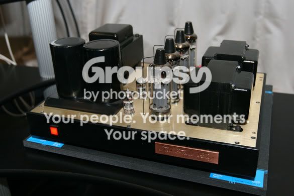
This is my Pentode Ultralinear coupled amplifier pumping 85W from 300V plate supply and able to drive any impedance from 3ohm and up in the same outlet. I call it *The Final Amp* Due to the low voltage the 2 big capacitors are parallel coupled which results in 3000uF and it can sure use them all. It contains no normal audio tubes´...I invented it 28 years ago and it might be the only of its kind in the world.

TheFinalAmp.jpg
 
Last edited:
I've seen several places in this forum theres a little confusion about 4,8,16 ohm outlet on tube amps (no offence). There is a reason why these outlets should be connected with corresponding impedance. If we look at 6CA7/EL34 so when it was invented inventors calculate an appropriate impedance of this tube with regard to the tube properties. This refers to maximum cathode current, plate power dissepation, saturation point etc.


Here are the data as many amplifiers are designed to follow ..

Typical class AB amplifier operation
(Er Values ​​for two tubes)
Power output: 55W
Plate resistance:
(Plate to Plate) 3.4 k Ohms
Plate voltage: 420V
Plate current: 120mA * 2
Screen voltage: 375V
Bias voltage:-38V
reference
Tung-Sol 6CA7 (EL34 Substitute) Vacuum Tube Logic Book 2nd Edition, 1994, page 151

Please note the plate matching load 3.4 Kohm ... it means that the speakers should be 3.4 Kohm to match the tubes. This is where the output transformer comes in. If we use 8ohm outlet with 8 ohms speaker the tubes se the right impedance (3.4K), but if you put a 4ohm speaker at 8 ohms outlet the resulting impedance of the tubes be divided by 2 (1,7k) and the tubes goes direct into forbidden area resulting more distortion, shorter tube life.

At low volume the 4 ohms speaker are louder at 8oms outlet, but you cannot achieve rated power due to tube mismatch and saturation.

Thats why its best to use the matching outlets.

Best Regards
 
Last edited:
I've seen several places in this forum theres a little confusion about 4,8,16 ohm outlet on tube amps. There is a reason why these outlets should be connected with corresponding impedance.

Please note the plate matching load 3.4 Kohm ... it means that the speakers should be 3.4 Kohm to match the tubes. This is where the output transformer comes in. If we use 8ohm outlet with 8 ohms speaker the tubes se the right impedance (3.4K), but if you put a 4ohm speaker at 8 ohms outlet the resulting impedance of the tubes be divided by 2 (1,7k) and the tubes goes direct into forbidden area resulting shorter tube life.

At low volume the 4 ohms speaker are louder at 8oms outlet, but you cannot achieve rated power due to tube mismatch and saturation.

Thats why its best to use the matching outlets.

Best Regards

This is a bit too simplistic. In the real world the speaker impedance is not some static value. It changes with the frequency of the signal being amplified. So the output tube and the speaker are rarely so equally matched.
 
Thats correct...its just to make theory clear about 4,8,16. I know speakers are not just 4,8ohms etc but we must try to match anyhow...I like happy tubes:music:...when they are not due to mismatch they tend to glow on the plate...then they are unhappy and so am I:tears:

If a speaker vary from 3- 25ohm (not uncommon) it would be an advantage to use the 4 ohms outlet...its very often in the bas the low impedance exist (not always) and its here the most power is needed.... A speaker like this I would not recomment due to the relativily low damping factor at most tube amps...

I hope this make sense...
 
Last edited:
Thats correct...its just to make theory clear about 4,8,16. I know speakers are not just 4,8ohms etc but we must try to match anyhow...I like happy tubes:music:...when they are not due to mismatch they tend to glow on the plate...then they are unhappy and so am I:tears:

If a speaker vary from 3- 25ohm (not uncommon) it would be an advantage to use the 4 ohms outlet...its very often in the bas the low impedance exist (not always) and its here the most power is needed.... A speaker like this I would not recomment due to the relativily low damping factor at most tube amps...

I hope this make sense...

The current wisdom of this forum seems to be, to try the tap that sounds best to you, the listener. I have never heard of anyone redplating from this practice.
 
Or something else...??


What are the dangers of hooking up the wrong speakers to an amp?

Too low impedance, for instance a 2 ohm speaker cabinet hooked up to an amp expecting 8 ohms, will overload the output tubes and the output transformer. The lower impedance will force lots of amperage through the tubes and out through the transformer. You would get a very loud amp for a short period of time. Something would blow. The tubes probably would go first, but you could also blow the output transformer or the speakers. It is possible that a small power transformer would not take the high amperage and blow up.
 
True but I don't know of any home speaker system that is a 2ohm set-up. I agree that there could be potential damage in some unfortunate blunders, but impedances vary greatly with frequency/ voltage , and the/your amp is likely to exhibit a strange personality before giving up the ghost(from driving speaks). This would be enough for the average person(hopefully) to pull the plug before things get ugly.
No offense!
Mike
 
Back
Top Bottom