• The move to the new server is done. There are some software and database maintenance updates in process. This has us passing the hat around to help out. We appreciate any donations. Seriously, even a dollar helps. The payment page may be found here - https://www.audiokarma.org/support.html

Hummm...

Ziradog

AK Subscriber
Subscriber
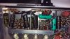
Not the bass (60 Hz) kind, more like the baritone (120 Hz) kind. Heathkit SA-2 integrated amp. I just replaced all the electrolytic, paper, & oil caps, and some resistors. Tubes are all back in their original positions. Now I have a fairly loud (noticeable @ 6 - 8 feet away from not-very-efficient speakers) hum. It is in both channels, constant volume regardless of the input selected, output selected, volume or tone control setting. I have rechecked all my work, and all the solder joints, so far no luck. Transformers & rectifier tube are all running cool, no other issues except that the phase reverse switch doesn't work (reversed gives no sound). Thoughts on where to start?
 
Register to hide this ad
The can cap was getting hot, one of the molded caps looked like it was leaking, and it had a bunch of the paper electrolytic's that are routinely recommended to be replaced.
 
Go back thru it systematically, look for bad solder joints, or solder clumps touching something they shouldn't, connections on wrong lugs, or wires,,,, make sure all grounds are in the same location as original... lytics installed backwards would probably be a worse problem than hum, but check it also... Also check that the new components are the proper value, I check new resistors with DMM before installing, as color bands can be hard to read... Carefully probe each connection with a stick, and see if the noise changes, it may be something that got disconnected or moved you didn't noticed while working...
I usually change em one at at a time and run the amp, just to avoid this problem...
Good luck...
 
Last edited:
This thing has an interesting ground layout. The is a rail connected to the chassis at 2 points. It passes through & is soldered to lugs at several points, with the component grounding connectsions going mainly to the lugs, a few directly to the rail. One lug has 8 wires soldered to it! I used the same ground points for each component. I have rechecked the orientation of all the electrolytics (except the ones inside the can but will do so again. I visually checked & "poked" all the grounds I touched, but I guess I need to check the other ones too and maybe re-flow those joints. I did check the new resistors with a DMM before installing them. I did not check the caps.

And yes, I know I shoudl do one component at a time & test it. I have been able to get away with not doing that before & this time I got bit. I am always afarid I will forget to disconnect the power between steps at some point if I keep powering it up & back.
 
If it's 120 Hz hum and occurs equally in both channels, I'm thinking the problem is related to the power supply, and it could be related to a ground issue on one of those filter caps you replaced, or related to the CT on the power transformer not properly grounded, or a combination of those things. A scope would be handy at this point to try to narrow it down.

Perhaps an obvious question, and totally asked out of lack of knowledge for the specifics of this amp, but sometimes those old caps have the can housing itself as the ground connection via the twist fastener to the chassis. More modern can caps have a lug or pin that is the ground. Basically just asking if you are 100% sure the ground leads, pins, or lugs on your new power supply caps are really grounded.

A leaky coupling cap could also cause this kind of hum, but usually associated with that is red plating or stage voltages that are off by a good margin.

One place to start would be to measure DC voltages on each pin of each tube. Sanity check those against the schematic. That may give you some clues. If you can narrow it down to one stage that is causing this or one stage that is out of whack some how, you're half way there.
 
I bought a replacement can cap from Hayseed Hamfest (a first for me). It does ground through the case/twist lugs. The capacitor case is insulated from the chassis. One lug is soldered to the ground rail, and I re-soldered it again tonight. One other lug is soldered to the center tap of the power transformer. I did replace all the coupling caps with new Illinois film caps.. I do have a (simple) oscilloscope, but still learning how to use it, what are you suggesting? I had not thought of checking the voltages, seems like a good idea since I am not seeing anything this way.
 
One thing to try then is take an alligator lead and clip one end to the ground bus bar and the other end to the ground of that Hayseed cap. See if that changes anything. By the way, it may just be luck of the draw that the Hayseed cap is bad, meaning internally one of the cap sections inside is either not connected to the positive lead, or the negative side of one of the caps is not connected to the case. (Nothing against this manufacturer, it's just you don't want to rule out any possible problem as you hunt.)

With the scope, you are looking for ripple that seems out of the ordinary. By examining the voltage at the input into each tube, you could visually see where hum is introduced. You could also use the scope to examine the ripple at each stage of the power supply (i.e, at the positive pin of each filter cap). The ripple at the positive pin of C25 should look like a sawtooth wave with peak to peak voltage variation of about 10 volts. The ripple at the rest of the power supply tap points should look more sinusoidal with the ripple at the positive pin of C24 maybe 100mV, C23 about 1mV, and C22 about 0.5mV. The exact numbers are not important, but rather the relative ripple reduction as compared to the previous tap point.
 
Played a little more with it tonight. I did find one loose wire but re-soldering it did nothing. I also tried the jumper from the ground bar to the can cap, did not help. I attempted to use my oscilloscope with little success. After 30 minutes with the manual, it appears that I can't set the sensitivity (v/div) and the Y-axis offset such to be able to measure the ripple current. Visually, it did go down at each cap. I checked the voltages on the transformer. Line in was 120.1 VAC. The 620 V winding actually measured 648. The 5 volt winding measured 5.2 VAC. The 2 filament windings measured 6.4 & 6.5 volt. Pin 8 on the rectifier measured right on 390 DC. Pins 4 & 6 were 324 (should be 310). Voltage at C35 was 389, C24 was 329, C23 was 246, & C23 was 191 - all within a couple % of the schematic. On the output tubes, Pin 2 measured 0 - .15 volts (should be 0). Pin 3 was 15 volts vs. 16 on the print. Pin 7 measured 383 - 388 vs. 385. Pin 9 measured 384 - 389 vs 390. More variation tube to tube than I expected, but otherwise not terrible.
 
Set it to AC coupling. That will get you where you can read stuff. The DC won't matter, its just the AC that needs looking at. Might need an x10 probe, but I doubt it.
 
From C25 to C24 the ripple should have gone down by something like a factor of 100 (a ball bark guess). And then from C24 to C23, ripple should go down again by a factor of another 100 or so (again a ballpark guess). If that's happening, then I'd say your can cap is working well enough anyway to not be the source of the problem. Most scopes cannot measure 1mV very well (can't distinguish from noise), but say on the 50 mV/div or the 20mV/div setting if the ripple as measured on C23 looks flatlined or nearly flatlined, it says to me those caps are working fine. Oh, also you should set the horizontal scale to 5ms/div or 2 ms/div if measuring 120 Hz noise.

If all that checks out (more or less), then I'd say the problem lies elsewhere, which is actually good to know, as at least you've eliminated one potential source of the problem.

Also now that the scope is warmed up, you might want to put the probe across a resistive dummy load that is connected to the speaker terminals and measure the hum frequency. Would be good to validate it's 120 Hz. 120 Hz hum will have a wave form that repeats every 8.333 milliseconds.
 
Last edited:
It will be next week before I can work on the amp again. Hopefully I can get the scope to do what I want then. Or maybe borrow a real one from work. I am confident that the hum is 120 Hz, I checked it with a chromatic tuner. I also played a 120 Hz sine wave through the amp to compare.
 
Are the secondaries of your outputs black wires grounded to the circuit ground? I made that mistake once and got what sounded like 120hz or so. Just a thought, if not that, other grounds.
 
I have not messed with the transformer wires but will double check.

I did figure out that my oscilloscope does not have an AC coupling mode. I have read that I can put a .1 mfd cap in series with the probe but I have not tried it.
 
What kind of scope do you have? AC coupling has been a pretty standard thing for a long time now.

A cap would do to block the DC. Thats about all the AC coupling mode is really.
 
Back
Top Bottom