
• The move to the new server is done. There are some software and database maintenance updates in process. This has us passing the hat around to help out. We appreciate any donations. Seriously, even a dollar helps. The payment page may be found here - https://www.audiokarma.org/support.html

I Bought The Wrong Power Supply Choke For My Vintage Tube Radio - Help

Henry Finley

Active Member
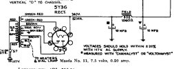
Ok, so this is not an antique radio site, but I'm sure crossovers do happen, so I'm giving it a shot. The radio is a 1940 RCA console radio, and the speaker field coil is no good. So I'm switching to a PM speaker. But I need a choke to make up for the field coil. A resistor alone won't do, because the field coil was part of the power supply filtering. Being a natural dunderhead I bought a Hammond choke with the right resistance, but the current ration is too low, and the choke heats up pretty quickly. So, here are the parameters in the attachments. Perhaps better (and younger) minds can come up with a solution. Thank you. Edit: The choke I bought was Hammond 155J
 

Attachments

  • power supply.jpg
    power supply.jpg
    57.9 KB · Views: 16
  • chokes.pdf
    chokes.pdf
    399 KB · Views: 8
Register to hide this ad
Ok, so this is not an antique radio site, but I'm sure crossovers do happen, so I'm giving it a shot. The radio is a 1940 RCA console radio, and the speaker field coil is no good. So I'm switching to a PM speaker. But I need a choke to make up for the field coil. A resistor alone won't do, because the field coil was part of the power supply filtering. Being a natural dunderhead I bought a Hammond choke with the right resistance, but the current ration is too low, and the choke heats up pretty quickly. So, here are the parameters in the attachments. Perhaps better (and younger) minds can come up with a solution. Thank you. Edit: The choke I bought was Hammond 155J
The one you bought is rated for less than half the current needed.
Your power supply Schematic shows a max amperage draw of 82ma.
So the 160 ohm 30ma choke would get hot.
 
I know. It was a blunder. Looking at the Hammond list, I'm thinking maybe model 156M, which leaves me needing about a 900 ohm wirewound in series with it. The Henrys aren't nearly as important. Even 3H would do. But if this new plan cuts the mustard with others on here, what wattage wirewound (or other) would I need?
 
honestly I'd just sub the entire thing with two 560 ohm in series. Bump the first cap to 22uF, 47uF to ground at the junction of the two resistors, and another 47 replacing the original second cap. That should give plenty of filtering without having to buy a choke.

current squared times resistance = DC power dissipation plus there is some AC ripple current involved. Basically double that calculated for an appropriate de-rate on the resistor. Its 3.8 watts DC dissipation per if you do a pair of 560, so you'd want at least a 7 watt resistor in that spot.
 
Man I like that plan. Who says you can't ask old radio questions on this site? Except for the 7 watt bit. Right now, I'm temporarily using a 1.1K ohm 25 watt wirewound, and it gets HOT in seconds. And I mean HOT!
 
Tube power supply's "R" AK~~!

You posted to the right site!
We'll see. I'll try bringing more of my "business" here. I've also got a BC348R from a WWII bomber receiver going on, and need to come up with a good 230VDC diode rectified power supply for it. I've heard it runs about 70ma with its original (missing) dynamotor, but there's no confirmation on that current rating.
 
LOL, My good friend is a Mil-Spec Nerd!

I just gave him another Dynamotor. But you DON'T want to be running one of those.

He was using a BC348 with a R390 as stages for a VLF receiver around 50Khz.

Cool...
 
Man I like that plan. Who says you can't ask old radio questions on this site? Except for the 7 watt bit. Right now, I'm temporarily using a 1.1K ohm 25 watt wirewound, and it gets HOT in seconds. And I mean HOT!
Is it one of those wirewounds encased in aluminum with stubby fins running down the sides and a mounting hole on each end? If so it should be mounted right to the chassis for more heat dissipation. I usually add a bit of thermal grease for good measure.
 
ight now, I'm temporarily using a 1.1K ohm 25 watt wirewound, and it gets HOT in seconds. And I mean HOT!
if thats a chassis mount job, they are only 25 watt rated when properly attached to a suitable size heat sink. They massively de-rate when on no or an undersized heat sink. May be worth measuring voltage drop across it to confirm that current flow number too since thats going to have a lot to do with heat output. Voltage drop squared divided by 1100 ohms will be DC dissipation, plus however much ripple current is present so it will be higher than just a straight calculation provides. If you measured AC across it and did the same math, then add that number to the DC number it will be pretty accurate if the meter is a true RMS type. Less so otherwise since it won't be a proper sine wave for the ripple.

Assuming the schematic is accurate though, 82mA across 1.1K is 7.4 watts of dissipation, and thats going to get reasonably toasty.
 
if thats a chassis mount job, they are only 25 watt rated when properly attached to a suitable size heat sink. They massively de-rate when on no or an undersized heat sink. May be worth measuring voltage drop across it to confirm that current flow number too since thats going to have a lot to do with heat output. Voltage drop squared divided by 1100 ohms will be DC dissipation, plus however much ripple current is present so it will be higher than just a straight calculation provides. If you measured AC across it and did the same math, then add that number to the DC number it will be pretty accurate if the meter is a true RMS type. Less so otherwise since it won't be a proper sine wave for the ripple.

Assuming the schematic is accurate though, 82mA across 1.1K is 7.4 watts of dissipation, and thats going to get reasonably toasty.
The 1.1K 25 watt wirewound resistor is not a chassis mount. It's an "ordinary" ceramic one that I call a sandy resistor. About 3 inches long, I suppose, and maybe equal 7/6 inch sides with sharp (not rounded) corners. Without me taking a picture and posting it, I suppose you know what I'm talking about. If I can just use that in place of the missing speaker field coil, and bump up the filter capacitance, I'll do it. But I suppose I'd need to use a couple stand-offs on the top side of the chassis to get the thing up so air can get around it. I'd hate to trap it from any kind of circulation on the underside of the chassis. I'd hate to think how it would turn that enclosed area into a furnace and bake everything.
 
Last edited:
yea I know the type. Those still get hot but at least 25 watts means 25 watts. Confirming the voltage drop and dissipation would be worth doing, just in case there is some other problem as well.
 
yea I know the type. Those still get hot but at least 25 watts means 25 watts. Confirming the voltage drop and dissipation would be worth doing, just in case there is some other problem as well.
I don't know whatever problem there could be. If it was stated that 7 watters would do, and I believe that poster knew what he was talking about. And mine is 25 watt, then it would just about HAVE to be fine. Right now I'm in the middle of completely overhauling the chassis. It was in VERY bad shape. I'm going through it replacing capacitors and a lot of resistors. In the meantime I stop to test it every so often, with the resistor and output transformer just hooked up with alligator clip leads, sitting on top of the Tombstone Pizza box I opened up and am using as a mat to protect the tabletop. So I suppose I could keep working. And once it's done, I suppose I could let the radio just sit there and run a couple hours with that resistor sitting on the cardboard mat. If the resistor doesn't go up in smoke, or scorch the mat, I suppose I could just mount it on top of the chassis and call the job done. I've been working on electronics a lot of years. But every time I deal with something that gets hot like this, I get skittish. This is a hobby that can give you some sudden frightening surprises that scare the daylights out of you.
 
I was making calcs based on what's on the schematic, but its worth confirming those values
I think I'm just going to go with it, because it's all right here. Every time some little thing is needed, you have to order it and pay shipping and wait a week, forcing you to clear the project off the table for something else while you cool your heels waiting on some picky little part. It's a lot easier to just get it done and if the house burns down, come looking for the dirty rat who gave the advice. Except I have an idea you know what you're talking about, so that's good enough for me. Wirewound sandys get hot. Duh. Just seems strange that a little bitty oblong block can replace the huge field coil on that 12 inch speaker. But I suppose the speaker field coil got pretty hot too. I have an RCA Crestwood I restored a couple years ago with a field coil 12 inch speaker. It would play about 20 minutes and start getting bad distortion. I surmised that the field coil was heating up and causing the voice coil to go shorty. So i got a used 12 inch 8 ohm ebay speaker and bought an output transformer to match it and the tubes, and just let the old 12 inch speaker lay inside the cabinet with it's field coil still hooked up. I've played that Crestwood for a jillion hours since then. But on this RCA, the mice chewed up the field coil, and I've been playing guessing games ever since. I could also buy a chassis mount 25 watt (or higher I suppose). But the impedances available are not what I need. So I'd have to buy a higher impedance one and jumper it with a wirewound to trim the value. Or buy 2 lower impedance ones and put them in series, and bolt them to the chassis and turn it into a blazing hot box. Once you lose your original field coil speaker, you're in for a world of hurt. But that's radio. Not a hobby for the weak-of-mind.
 
my greater point here is that confirming the current flow via voltage drop across the resistor would rule out any deeper problems and verify that the 25 watt resistor is sufficient without having to guess at it. It certainly should be, but if something else is wrong and causing excessive current flow it will get even hotter until that problem is fixed.
 
If it's any help I put my volt meter across that resistor it it said 70VDC. but I didn't know what I was expecting to achieve doing that. But so far, I've only restuffed the can cap and changed a couple paper caps and a few resistors so far. I can't know anything until the think is completely overhauled. The radio is (was) in F- condition. It really does just belong out on the curb for the garbage truck. We'll see. And I thank the forum for its help. I'll report back.
 
70V / 1100R = 64mA, so lower than the schematic calls for. May indicate slightly tired tubes, but thats generally less of a problem than excessive current. Its doing about 4.5 watts.
 
I meant to say 80 volts, but its fine either way. Every tube in this thing is weak as a kitten, testing about the value stated in the Hickok 752 tube chart. But should be good enough to get this thing up and running. I suppose even 4-5 watts will heat up a 25 watt wirewound right toasty. So I'm going to proceed with the recap, resistor job and see how it plays, with confidence about this resistor. I still doubt I'll stick it on the underside of the chassis. There's a nice open piece of real estate up on the front top of the chassis. I'll stick the audio transformer and resistor there. You'd have to be pretty stupid to reach back in there and fiddle around touching the chassis anyway when its running. This thing is such a piece of rusty junk. You should see the cabinet. F--. Garbage truck quality. I can't thank you enough. Right now I can get one local AM station, barely audible at full volume. Maybe the overhaul will perk it up. Or I could take up golf. But I'd rather go to the dentist and have a tooth pulled. I fix broken things.
 
Back
Top Bottom