gaboozo99
Vinny Bag o' Pins
HI everyone. Been some time since I've had to post here looking for some help, but I had a dear friend bequeath to me his Marantz 2325 and I've had a rebuild kit in my hands for the better part of the year sitting in a box. Now that the worst of the summer heat is over with, and my garage is a somewhat friendly working environment, I decided to get to work. This 2325 is not my first rodeo. I've rebuilt and repaired several other Marantz and Pioneer receivers of the day, and know my way around a soldering iron and multimeter. I even have a logic probe..ooooooohh, ahhhhh. SO I'm competent in through hole board repair, been doing this on Arcade equipment for over 25 years as well.
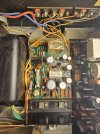
To start, the 2325 was functioning. Meaning it had sound from both left and right channels, it would tune to FM and AM stations and in general terms all the functions seemed to do what they were supposed to do. Volume was intermittent at low levels, and it took turning it up at least a 3rd of the way to get sound from both left and right channels. But once playing, it would do so for plenty of time with out issue. Several hours at least if it was behaving. So armed with what I thought was a working receiver, some really dirty controls, and a bunch of burnt out lamps etc. I dove in. Rebuilt the power supply, all new electrolytic caps, new LY2 relay (had to wait for that a couple days, and more on why that was an issue) new TIP 41 transistors with new thermal paste and all mica insulators and heat shrink insulators installed again etc. No issues. Some slight lifting of the relay traces, but nothing that was severed from the circuits themselves. This receiver is all original, no previous work, and is fairly clean. Double checked polarity of the caps with the board markings AND the before pics I took just to ensure they matched the originals. The parts are from a kit (fairly reputable ebay seller,) and I verified each cap was correct impedance and in all cases higher voltage values. Kit parts were broken down by board, so only the Power supply parts were taken out of the bag marked "Power supply" Provided instructions were only helpful in keeping track of which parts I replaced, along with a marking on the sheet. Not that the PS is that complex anyway. Ok here's the issue. I don't have a copy of the schematics or service manual. Seems HiFi Engine no longer knows my User ID or password and isn't accepting new members. So Even the link provided by the ebay seller takes me to a log in, and I figured, when I need to do the adjustments I'll just look those up and do so when needed. Besides that the kit had the wrong relay so while I waited for the correct one to arrive, I had the right channel amp already uninstalled and figured, well I'll just do that one while I'm waiting.
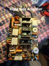
Same deal, replaced electrolytics, all the smaller transistors, and 4 diodes plus the flyback diodes, put together a differential pair with thermal grease and a bit of heatshrink to keep them together, etc. etc. Also added the flyback diodes (in opposing directions) as this unit is an early production unit and didn't' have them. Made sure to check out pictures, and installed them to the correct resistor leads, and leads on the board. Not really difficult stuff here, and all the work was cleaned, solder pads checked, figured easy peasy.
Got the relay a day later, installed it in a couple minutes, put the right channel amp back plugged it in with the 4 pin Molex and cleaned RCA type plug and set it all up on a dim bulb tester with a 100w bulb. Flipped the switch, all came on as expected, no issues, no smoke, etc. Took it off the dim bulb, turned it back on, and tried to get sound. Got sound out of the left side only. Tried fader back and forth, and while all the way to the right I can get very faint sound from the left channel when volume is turned way up, but the right side is silent. Dead silent.
Ok so at this point I know I need to get out some test equipment and start checking voltages and see whether I have a power supply issue or an amp issue. Did a quick test of the output to the amps.. J809 (blue wire) on P800 power supply has 11.7 mV, and J808 (yellow wire) on P800 has 174 mV. (Big discrepancy here) Voltages on the P800 board check out. J806 19.81V, J807 13.02V, (a little low?) J805 34.96V. Voltages at the amps find plus and minus 62.2 V at both left and right sides, so those look good as well. Tried connecting and cross connecting the Pre In with output via RCA cables, no change. Only the left side channel has sound.
Figured maybe someone with more intimate knowledge than I could start to point me in the right direction. Just grabbed the Service manual and schematics off AK's PDF database, (TY AK!) At this point before I start really digging in, I figured I better get prepared so I can get this done correctly. My buddy deserves to know his prized amp is singing once again and being enjoyed down here on Earth. I know he'll be happy when that day comes!
Thanks in advance.
Vinny
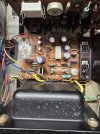
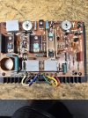
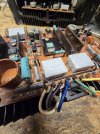

To start, the 2325 was functioning. Meaning it had sound from both left and right channels, it would tune to FM and AM stations and in general terms all the functions seemed to do what they were supposed to do. Volume was intermittent at low levels, and it took turning it up at least a 3rd of the way to get sound from both left and right channels. But once playing, it would do so for plenty of time with out issue. Several hours at least if it was behaving. So armed with what I thought was a working receiver, some really dirty controls, and a bunch of burnt out lamps etc. I dove in. Rebuilt the power supply, all new electrolytic caps, new LY2 relay (had to wait for that a couple days, and more on why that was an issue) new TIP 41 transistors with new thermal paste and all mica insulators and heat shrink insulators installed again etc. No issues. Some slight lifting of the relay traces, but nothing that was severed from the circuits themselves. This receiver is all original, no previous work, and is fairly clean. Double checked polarity of the caps with the board markings AND the before pics I took just to ensure they matched the originals. The parts are from a kit (fairly reputable ebay seller,) and I verified each cap was correct impedance and in all cases higher voltage values. Kit parts were broken down by board, so only the Power supply parts were taken out of the bag marked "Power supply" Provided instructions were only helpful in keeping track of which parts I replaced, along with a marking on the sheet. Not that the PS is that complex anyway. Ok here's the issue. I don't have a copy of the schematics or service manual. Seems HiFi Engine no longer knows my User ID or password and isn't accepting new members. So Even the link provided by the ebay seller takes me to a log in, and I figured, when I need to do the adjustments I'll just look those up and do so when needed. Besides that the kit had the wrong relay so while I waited for the correct one to arrive, I had the right channel amp already uninstalled and figured, well I'll just do that one while I'm waiting.
Same deal, replaced electrolytics, all the smaller transistors, and 4 diodes plus the flyback diodes, put together a differential pair with thermal grease and a bit of heatshrink to keep them together, etc. etc. Also added the flyback diodes (in opposing directions) as this unit is an early production unit and didn't' have them. Made sure to check out pictures, and installed them to the correct resistor leads, and leads on the board. Not really difficult stuff here, and all the work was cleaned, solder pads checked, figured easy peasy.
Got the relay a day later, installed it in a couple minutes, put the right channel amp back plugged it in with the 4 pin Molex and cleaned RCA type plug and set it all up on a dim bulb tester with a 100w bulb. Flipped the switch, all came on as expected, no issues, no smoke, etc. Took it off the dim bulb, turned it back on, and tried to get sound. Got sound out of the left side only. Tried fader back and forth, and while all the way to the right I can get very faint sound from the left channel when volume is turned way up, but the right side is silent. Dead silent.
Ok so at this point I know I need to get out some test equipment and start checking voltages and see whether I have a power supply issue or an amp issue. Did a quick test of the output to the amps.. J809 (blue wire) on P800 power supply has 11.7 mV, and J808 (yellow wire) on P800 has 174 mV. (Big discrepancy here) Voltages on the P800 board check out. J806 19.81V, J807 13.02V, (a little low?) J805 34.96V. Voltages at the amps find plus and minus 62.2 V at both left and right sides, so those look good as well. Tried connecting and cross connecting the Pre In with output via RCA cables, no change. Only the left side channel has sound.
Figured maybe someone with more intimate knowledge than I could start to point me in the right direction. Just grabbed the Service manual and schematics off AK's PDF database, (TY AK!) At this point before I start really digging in, I figured I better get prepared so I can get this done correctly. My buddy deserves to know his prized amp is singing once again and being enjoyed down here on Earth. I know he'll be happy when that day comes!
Thanks in advance.
Vinny