• The move to the new server is done. There are some software and database maintenance updates in process. This has us passing the hat around to help out. We appreciate any donations. Seriously, even a dollar helps. The payment page may be found here - https://www.audiokarma.org/support.html

I was bored this winter and did a small DIY project

This is my first amp, I studied both Cordell and Self. I experiment with very high loop gain this time, just one way to start. I just want to finish one amp first and then plan on others later. I finished my first version on a wood board and did extensive comparison as shown in this thread: http://audiokarma.org/forums/index.php?threads/does-a-good-and-expensive-amp-matters.757185/

My amp is complementary IPS with current source load, darlington VAS and tripled EF OPS with high current bias satisfying Oliver's condition. The Nakamichi is the Stasis design with no GNFB. Two polar opposite design sounded exactly the same. That make me question how important is the power amp if they are beyond certain standard. I don't know, only way is to build another one polar opposite like the Aleph by Pass. And then a tube and compare.

I need to study and simulate the Technics circuit after my amp is completed. I did research a few patents and simulated them, absolutely no luck, the distortion is very high in different ways, my conclusion is there is no free lunch. Particularly when I adjust the bias and look at the FFT, it's really not as much difference as I expected. Between Oliver's condition to class A, difference is really minimal. If FFT shows minimal difference, From my extensive experiment, I doubt I can hear any difference.

I don't know the group delay, but my amp is also very fast, large signal rise time is like 0.8uS and no noticeable overshoot with 4ohm load. But there's just no difference in listening. You see in my thread I experimented with 3 pairs of speakers. The speakers sounded day and night difference, but identical between the two amps. The more disheartening thing is the Acurus 200X3 that is supposed to be much lower grade, sounded very closed that I had to switch back and fore quite a few times to make the claim.

I am actually thinking about lowering the idle current, change the emitter resistor from 0.27ohm to 0.33ohm or higher to meet the Oliver's condition and run the FFT and see how much different is the THD. That way I can raise the rail voltage to get more power to avoid clipping all together. I was on DIYaudio before, people like the popular Honey Badger and a few others all run lower idle and keep at class AB and raise the rail voltage and speed up the amp. This is their concept and they apparently are very successful. Maybe there is some truth on that. I am experimenting towards that.

EDIT:

For the fun of it, I just did experiment with emitter resistor of 0.27ohm that the oliver's condition is about 100mA/stage and 0.09A total idle current. I run 10KHz, output is 22V peak ( 44Vpp or 15.5Vrms), the rail is 31V with bench top supply, driving 4ohm load. So I am driving 60W with +/-31V rail, that's quite high already.

I lowered the idle current down to 0.6A, THD is 0.01034%, I then raise up to 2A and THD is 0.00975%. At 1A, it's about 0.01005%. So you see very little distortion change with big change in idle current. This make me question all the fuzz about the idle current as long as you get a little of class A in the middle.

Maybe the key is to have lots of output stages. Self showed distortion is minimal if load is above 32ohm driving by one stage. Which is 16ohm for two stages, 8ohm for 4stages and 4ohm for 8 stages.
 
Last edited:
Yes, I have seen your thread. I have some of Bob's and Douglas books as well. I use them as reference as they contain lots of info but by no means everything is covered in these books. The audio field is just way to big and is constantly evolving. By the sounds of if you are very much interested to design amps from scratch. If this is your main focus DIYAudio is a pretty good place to be. There are a few very knowledgeable and skilled people over there. If you are new to designing amps, don't expect to get it perfect on the first one. You might find it takes years or decades to get it perfect. The field is just way to big.;)
I am no sure what your goal is, the journey to learn the secrets of amps and design the perfect one or just to have something really good for listening. If you just want something to listen to that is pretty decent, pickup a Technics of ebay on the cheap, hook it up and judge for yourself. You got lots of expensive stuff to compare it to. You might find you are chasing a ghost or you find something better. It may save you a lot of time and aggravation and disappointments.
The some amplifiers make really good combo with certain speakers, some others not so much. Perhaps it is just a matter to find the perfect mate to the speaker.

The thing with patents is that not all the crucial info may be in the patent, just enough to get the patent granted. Some of the 'trade secrets' may not be in the patent at all but is crucial to make it work. I was privileged to work with one of the most brilliant chief engineers I have ever met until he retired and have seen what he put into his patents and what not (kW RF stuff). So I know first hand. Some of his tricks of the trade may have rubbed off on me, I guess. But that makes me by no means an expert in anything. I know just barely enough to get myself into trouble. I have witnessed him doing his magic and achieving a theoretical impossible spectrum purity on a 3MHz design. Text books and Professors at Universities insist otherwise. My chief engineer just shook his head and said, no wonder if they teach this crap to students that we are no longer advancing, smiles and holds a paper under my nose written by some Prof. Dr. xxx at Phillips and said to me, see all these equations in here ? They are all wrong. The conclusion in here all wrong. The only thing correct were all basic schematics. Then he proceeded to derive the equations himself and fed his simulator with it and achieving the theoretical impossible. Having all seen that myself I have now a slightly different view on things. I don't buy anything as face value only because it was printed and published. I take it with a grain of salt.;)

Group delay as I understand it is simply the time it takes the signal to propagate from the input and work its way through the circuit until stable output is achieved. If you already achieve 0.8us delay that is pretty good. If you can't hear any difference anymore then I'd say you have achieved everything you can unless the speakers are not good. But I am sure you have good speakers. Personally I would prefer some equipped with ribbons that do well in excess of 30kHz before rolling of at -3dB. It took me a while to find a good speaker for myself that does not bust the bank and satisfies that, so I ended up with vintage Pioneers DSS-7 equipped with Boron mids and Beryllium ribbon tweeters. Picked them up in mint condition for cheap, $75. I had XXXX (don't want to offend anybody) before and paid full fare on them, boy what a disaster. Using the same amplifier the XXXX (don't want to offend anybody) are really really bad, no highs too much mids and bloaty bass. Crappy stereo image and no brilliance, just dull mush for lots of $$$. Connecting the Pioneers DSS-7 and did A/B switch over I was shocked, difference like day and night, all of the sudden the stereo image opens up, I could hear details the XXXX (don't want to offend anybody) never did. Now I can hear if a MP3 plays or something not so lossy. Long story short, there is a whole lot of pretty looking expensive and hopelessly overrated stuff out there that is not worth a dime but looks pretty on a stack that it makes me dizzy. :confused:
Mind you when was it the last time you have seen a speaker manufacturer offer a distortion over frequency chart ? I know of only two manufactures that dare to publish such data since they have nothing to hide. What about others ? Why is it that some mfg offer at best a single figure for THD @ 1kHz ? Or try to impress with a humongous dampening factor ? TIM figures ? Because that is all they can barely achieve or dare to publish. :eek:

Anyway, feel free to PM me so this thread is not getting cluttered.
 
Thanks

I checked, the SE-A5 is like $900+shipping. I think I have enough amps for now, just wait until I finished this one first. I took a quick look at the circuit, other than the bias part, it's not a whole lot of difference from a convention amp. I might do a run of the ops board in the future.

Alan
 
Thanks

I took a quick look at the circuit, other than the bias part, it's not a whole lot of difference from a convention amp.

Alan

You may not realize it but right there you are looking at the crucial part that set this amp apart from the hopeless overpriced wannabees.

Remember it is about finesse not brute force !

I am sorry to hear you dismissed the possibility to try a New Class A.
 
You may not realize it but right there you are looking at the crucial part that set this amp apart from the hopeless overpriced wannabees.

Remember it is about finesse not brute force !

I am sorry to hear you dismissed the possibility to try a New Class A.
No, I am not dismissing it, I just want to finish the one I have. It's almost done. I am going to look into it, I am very interested in it, I even attempt to design my own version. I did simulations on the concept of a few patents. I am even thinking about doing a Aleph be Pass which has a load dependent source to keep operation is class A.( It's really a single ended design where the pull up is active and adjusted to current requirement of the load to keep it in class A.). I am definitely interested in how to extend the class A region without burning a lot of current.

I made a short remark in the last post as I don't want to further making long discussion in your thread on this. When I finish my first amp, I will be searching for something that is very different from that amp, one high loop gain is enough, I am going to go polar opposite and other concept, maybe like new class A or others, even tubes. I am just too busy to worry about it right at this moment.

Did you see my thread on my amp? I just got there last night. If you have any input in lowering THD at large signal above 10KHz, please join in.
 
Last edited:
Just want to confirm it's simulation only. What load are you using, also what is the amplitude? I'll be crying if this is real measurement on a real amp!!! I got 0.0066% THD into 4ohm with 22Vpp.....and Whopping 0.022% at 40Vpp!! In all fareness, I only have +/-30V rail as that's all my bench supply can give out. It's pretty large signal for such low rails.

I definitely going to analyze the the New Class A and run simulation with LTSpice.......after I completed my amp. I got to finish my amp and have at least one amp under my belt. When I was half way bringing up my first version, I got called for a contracting job by my former company that supposed to last two months............until it lasted one and half years!!! I just got back to finish up the first version and did the revision and bringing it up now. Nothing is going to stop me until I finish this. I even told the company don't call me for the next month and half. It's that important for me.

I am very interested in this new class A, if you have any other suggestions on other similar type of extending the class A region, I want to look into this more. I don't like the class D driving the rail to power the signal amp in the middle to keep the rail voltages low so the middle amp can run in class A. I believe there's no free lunch and is playing with fire if you wiggle the rails like this. I can see those power transistors oscillate like anything as they don't have a good AC ground at the collector and driven by a reactive(active) device.

EDIT:

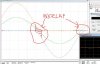
Question on the graph, are the two flattened sine wave(red and blue trace) the current conduction of the top and bottom transistors? If so, this is class AB only with some overlap at the crossover region. Just the tailing off is very smooth.

Overlap.JPG
 

Attachments

  • Overlap.JPG
    Overlap.JPG
    56.9 KB · Views: 3
Last edited:
Yes, sim only with 8 Ohm load, about 28Vpp.

Technics Class AA, which is profoundly different from the Technics New Class A uses the principle that was described by Dr. Sandman in which a pure Class A amplifier is combined with a pure Class B through a resistor bridge forming a new amplifier class, Class S. A very slick approach.

Check out this paper.
http://www.keith-snook.info/wireless-world-magazine/Wireless-World-1989/Evolutionary Audio.pdf
See page 11 figure 7 and figure 8 and let it sink in. :D

Technics SE-A100 :rockon:

EDIT:

Yes, 'fancy' Class A/AB
http://audiokarma.org/forums/index.php?attachments/overlap-jpg.899226/
 
Last edited:
Back
Top Bottom