• Please note that Audiokarma will be offline briefly for updates early on Monday morning, September 28th.

"IC" chips in a Proton 550?

Mark Shipton

New Member
This is an update on my recently purchased Proton 550 integrated. Upon inspection, left channel sends unit into protection shut down at anything over lowest volume, right channel perfect. Local electronic shop say's it needs "IC" chips, "about 3 inches long" costing about 65 each, repair estimate 180$. So I decide that I can get something better than this for 180 but decide to take it apart to get a look at these "IC" chips. Upon inspection... I see nothing fitting that description. I see 4 Sanken transistors, two 2SC2921 and two 2SA1215. These cost about 6$ each. So are these what my experts were calling "IC chips"? I'm wondering if I was being taken for a ride by these guys or if I'm just to stupid to locate the "chips" that need replacment? They said there were 2 of the IC chips one bad but both needing replacement , I see 4 flat transistors. Am I missing something? If not, I can replace all of these for next to nothing, or could I upgrade? I'm getting "the itch" now, and want to recap while I'm in there and get rid of the tone controls for more purity. Any guidance would get my undying gratitude for life.

Thanks
Mark
 
Register to hide this ad
pics of the Proton 550 (I hope)

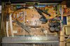
Ok, here's a couple of snaps of my board. I'm trying to figure out if there are "ic's" in this amp or just the transistors shown. Notice the heated area towards the right side of the board near the middle, also a few added resistors as "afterthoughts"? thanks
 

Attachments

  • back.jpg
    back.jpg
    118.3 KB · Views: 122
  • top.jpg
    top.jpg
    96.8 KB · Views: 128
Last edited:
I can't believe these people just out and out lied to me. I saw the lady pretend to look my chips up online and quipped out 65$ each... what a bunch of lowlifes! I'm going to go back and ask them why they told me things that were untrue.

Well, so good for me then. Now what should I do? Should I just replace the 4 Sankens with the same or is there something better? Then, should I just replace the 4 larger caps bunched together or are there more things I should be replacing? That area on the back I mentioned above that shows signs of heating along with an added on resistor looks a bit worriesome. This is first time around for me and will be a learning experience.

thanks
Mark...
 
2SC2921 and 2SA1215
Rather than just throw parts at it.First just locate and fix the problem...:yes: BEFORE modifying or recapping.
Each channel has one of each output . One is a NPN the other a PNP.You need to figure out which two are for the left channel. Remove the two from the circuit and check then with a DMM.
 
Last edited:
Ok will do, but would I be incorrect in assuming that the ones on the left would be the ones powering the left channel? My plan was to check the voltages on the pins while it was plugged in, and see if which side showed significantly lower values in any reading. I realize that is probably not the way to do it, call it intuitive, but could I damage something while taking readings with the unit powered on? I will do a search for "how to test transistors", but if it's easy enough to briefly explain here that would be appreciated.
 
Yes you can check the voltages on the transistors and compare the measured voltages to the schematic. Might want to first look the amp over real good and locate all the fuses and check them with a meter as well..
 
I got this for testing transistors:

* Connect the red (positive) lead to the base of the transistor. Connect the black (negative) lead to the emitter. A good NPN transistor will read a junction drop voltage of 0.4V to 0.9V. A good PNP transistor will read open.
* Leave the red meter lead on the base and move the black meter lead to the collector - the reading should be the same as the previous test, with a slightly less voltage drop in the forward direction.
* Reverse the meter leads and repeat the test. This time, connect the black meter lead to the base of the transistor and the red lead to the emitter. A good PNP transistor will read a junction drop voltage of 0.4V to 0.9V. A good NPN transistor will read open.
* Leave the black meter lead on the base and move the red lead to the collector - the reading should be the same as the previous test, with a slightly less voltage drop in the forward direction.
* Place one meter lead on the collector, the other on the emitter, then reverse. Both tests should read open for both NPN and PNP transistors.

Good?
 
Yep..That sounds like the procedure--Coll-emittr front/back--Coll-Base front/back and base-emittr front/back..:yes: Using the diode setting on the DMM..
 
When probing a powered circuit .. it would be wise to invest in a couple sets of mini-grabber clips. Shut off power - connect clip to test point and meter-turn power on- record meter reading-shut off power-proceed to next measurement point.
 
Well, given that I don't REALLY know how to test these while powered, it's easy enough to disconnect them and will follow the instructions above. Will post results, thanks much.
 
Well, that turned out pretty well... tested the transistors and they were ok, but a couple of the solder connections looked really crappy. So after a clean and lube, put the transistors back in and viola, music. Quite a change for the better though by bypassing the preamp circuit and using direct input via a cd player with a volume control, much more coherent. Combined with some new 19$ ebay Mission book shelf speeks, and wow, quite good, though I'm using about 900$ worth of cables and interconnects (don't even ask).

Thanks for the help, Avionic et. al.

Oh, and if anyone ever gets a chance to patronize "AT HOME ELECTRONICS" IN KENNEWICK WASHINGTON" they are a redneck bunch of stinking, damn liars, so don't.

mark...
 
Outstanding...:thmbsp: For $180 worth of bad chips...:scratch2:
 
Back
Top Bottom