• The move to the new server is done. There are some software and database maintenance updates in process. This has us passing the hat around to help out. We appreciate any donations. Seriously, even a dollar helps. The payment page may be found here - https://www.audiokarma.org/support.html

ID this early power amp

RuffzGuts

Super Member
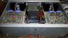
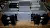
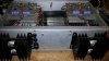
Well I picked up some interesting stuff at a garage sale over the weekend, one of the items was this beautifully constructed early solid state power amplifier :yes:

At first I thought it was home made, but after getting it home and having a better look at it, I believe it may be a kit of some kind.

I am hoping someone here may recognize the amp, and I would like to talk about options for possibly swapping out some of these older transistors.

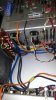
The underside houses 2x 2500uF 100v & 2x 8000uF 75v Elna filter caps per side....

It does have problems on one side....after replacing one of the 4 5A fuses I am able to run the amp and it sounds lovely but output transistors are heating up on that channel so need to look into it, it would be wonderful right now if I could ID this and hopefully find some kind of schematic....

Will post some pics up now, look forward to advice as usual, thanks in advance
 
Register to hide this ad
Power amp kit

pics
 

Attachments

  • POWER AMPLIFIER KIT BUILD 002.jpg
    POWER AMPLIFIER KIT BUILD 002.jpg
    67 KB · Views: 258
  • POWER AMPLIFIER KIT BUILD 003.jpg
    POWER AMPLIFIER KIT BUILD 003.jpg
    63.1 KB · Views: 234
  • POWER AMPLIFIER KIT BUILD 004.jpg
    POWER AMPLIFIER KIT BUILD 004.jpg
    65.7 KB · Views: 152
  • POWER AMPLIFIER KIT BUILD 005.jpg
    POWER AMPLIFIER KIT BUILD 005.jpg
    55.7 KB · Views: 119
  • POWER AMPLIFIER KIT BUILD 008.jpg
    POWER AMPLIFIER KIT BUILD 008.jpg
    57.3 KB · Views: 127
pics2

more pics...
 

Attachments

  • POWER AMPLIFIER KIT BUILD 009.jpg
    POWER AMPLIFIER KIT BUILD 009.jpg
    54.3 KB · Views: 108
  • POWER AMPLIFIER KIT BUILD 010.jpg
    POWER AMPLIFIER KIT BUILD 010.jpg
    67 KB · Views: 136
If I'm reading what I presume to be date codes on the output transistors correctly, thats not as old as you might think. Looks like week 26, 1980 if the "2680" means what it seems to.

Looks like it was built with a lot of 2% tolerance resistors too. Depending on how it works, I may be inclined to leave those old transistors in place. It does have a kit sort of look to it, but it looks to be a decently well made one at least.
 
Agree about the date codes on the TO-3's

Let's see the date codes on the caps.

The board mounted metal can RCA transistors are mid '70's. That's too much span for them to have all been included in a "kit".
 
The more that I look at it, there seems to be an inconsistency of parts used here, Transistors, Resistors, Power supply caps... the age as well as brand of different parts...

This is the first time I've seen this kind of metal can transistor used in an amplifier and just made the assumption that there are better options available now. Now after a little more research I see they are still readily available.

I think this may have been put together by someone in an industry where they had access to parts and equipment to build this....You could say it has been built by a pro audio amp builder, but then the parts inconsistency doesn't make sense.

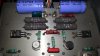
I will add there is no bottom plate on the amp, Boards are conductive (note solder directly to boards) ,there is no power switch although looks like a control plug at rear for a pre amp but it hasn't been wired in... everything here is quality, right down to the paint that has been used on the transformer...the soldering work is excellent, I really don't want to de solder anything I don't have to though I will need to cut some wires in order to flip these boards....

I think while I am there I will change out these 470uF SAM HWA caps for something better, suggestion? I am having trouble sourcing something suitable and may consider using radials...

I think if this turns out to be a nice amplifier, which I think its going to...I will consider making a new faceplate, possibly a glass lid...shift speaker terminals and rca ins to rear...maybe even fit VU meters......but then again, I may just leave it exactly how it is...
Again look forward to your thoughts and knowledge of what I have here, thanks
 
pics 3

more pics
 

Attachments

  • MORE POWER AMP KIT PICS # 005.jpg
    MORE POWER AMP KIT PICS # 005.jpg
    59.5 KB · Views: 47
  • MORE POWER AMP KIT PICS # 004.jpg
    MORE POWER AMP KIT PICS # 004.jpg
    58.9 KB · Views: 39
  • MORE POWER AMP KIT PICS # 003.jpg
    MORE POWER AMP KIT PICS # 003.jpg
    57.6 KB · Views: 40
  • MORE POWER AMP KIT PICS # 002.jpg
    MORE POWER AMP KIT PICS # 002.jpg
    52.8 KB · Views: 43
  • MORE POWER AMP KIT PICS # 001.jpg
    MORE POWER AMP KIT PICS # 001.jpg
    59.8 KB · Views: 58
and pics again

filter caps and rear side
 

Attachments

  • More POWER AMP KIT PICS 001.jpg
    More POWER AMP KIT PICS 001.jpg
    55.3 KB · Views: 72
  • More POWER AMP KIT PICS 002.jpg
    More POWER AMP KIT PICS 002.jpg
    64 KB · Views: 54
  • More POWER AMP KIT PICS 003.jpg
    More POWER AMP KIT PICS 003.jpg
    54.6 KB · Views: 50
  • More POWER AMP KIT PICS 004.jpg
    More POWER AMP KIT PICS 004.jpg
    63.9 KB · Views: 42
  • More POWER AMP KIT PICS 005.jpg
    More POWER AMP KIT PICS 005.jpg
    66 KB · Views: 44
centre bay

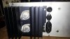
power cap terminals rectifiers fuses
 

Attachments

  • More POWER AMP KIT PICS 006.jpg
    More POWER AMP KIT PICS 006.jpg
    57.3 KB · Views: 73
The board mounted metal can RCA transistors are mid '70's. That's too much span for them to have all been included in a "kit".

Phase Linear was using those TO-92 type transistors in the early 80s still, so it still may be possible they are all original. My Pro 700 was built in mid 1982 and has 4 of them on the board.
 
The circuit boards have a Dr. Marshall Leach look to them. The Low TIM amp articles of the late 70s would have been out by 1980 and into the hands of DIY types.

Who ever did the build needs to be hired by someone - assuming he hasn't retired by now. Excellent build quality.

Cheers,

David
 
Well the good news is there is absolutely nothing wrong with this amp!

After checking over it I have steered toward the speakers it came with which are a score in them self's. “The Radio People” Spectrum tower speakers sporting 4x Audax / Polydax Model HIF 13 H drivers (15 Ohm), two as mids and two installed firing upward into a front ported bass chamber off a 3 way crossover with Audax / Polydax HD12 x 9 D25 tweeters....(-:

One of the bass drivers has a bad voice coil...so I may be looking for one or maybe a pair of these drivers...I think these speakers are worthy of another thread when I get the time...again beautifully constructed although in need of some minor work to the cabinets....

So the amp is running beautifully now through another set of speakers...Very happy..
I will still be looking at changing those caps out though as they have measured high...any suggestions very welcome
 
Last edited:
Looks like you have lots of real estate in there for main filter caps. Quite a few possibilities.
 
The circuit boards have a Dr. Marshall Leach look to them. The Low TIM amp articles of the late 70s would have been out by 1980 and into the hands of DIY types.

Who ever did the build needs to be hired by someone - assuming he hasn't retired by now. Excellent build quality.

Cheers,

David

I have been hunting the net all day trying to find anything like it to no avail.
The guy I bought it off was 60 odd and his story was that it was his fathers and he had no interest. I did question him about his father whom has passed, whether he was into electronics? to which he replied no... he did say that he had purchased the speakers for a high price in the 80's ( which obviously don't match this amp) and believed he may have been ripped off...but wasn't sure...
Who ever put this together definitely had passion for what he was doing..I hope he is still with us.

Looks like you have lots of real estate in there for main filter caps. Quite a few possibilities.

21000uf per channel, you think I need more? more than enough than I will ever need I think...There are lots of possibilities for mods, but at this point out of respect I don't want to mess with this amp to much..although I am still thinking I might re dress it...and shift plugs to rear...

Had a very big smile on my face all day listening to it and that's only through some average speakers, been hunting for a decent two channel power amp for a while now, next step to work out the true rms
 
The circuit boards have a Dr. Marshall Leach look to them. The Low TIM amp articles of the late 70s would have been out by 1980 and into the hands of DIY types.

Who ever did the build needs to be hired by someone - assuming he hasn't retired by now. Excellent build quality.

Cheers,

David

What makes you say Dr. Marshall Leach?

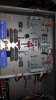
Regarding these circuit boards? has anyone ever seen anything like this in any other application?
 
Although not really into audio then, I salvaged a lot of old components as a kid.

The small brown resistors used (the small ones) existed already more than 40 years ago, as I was salvaging them from scrap early computer boards. Those boards were sold by a guy on the (then) famous Amsterdam "Waterlooplein" flymarket, where he was taking off all the goldplated edge connectors and sold the electronics. They are metal film ones, with copper ends and those funny 4 holes in there. (nothing sticks to your magnet).

Some mil spec resistors will look the same, apart from text instead of color coding.

So, you see American stuff except maybe those Elna and the red capacitors?

When this amp was made, production cost was not an objective, this one could not be made for a normal price.
This kind of circuit cards you will want to find in high end audio, guess one rarely does.

I edited this post again, because by looking closer at the pictures, the circuit cards could be made by a very professional hobbyist with some facilities around.
 
Last edited:
This ain't the product of any diy'er but of a pro. Looking at the board etching and the component lead bends, wiring etc. all points to a professional engineering prototype. Maybe a startup that never got off the ground or something from one of the famous engineers that went on to be some other final product.
 
Are those circuit boards made of sheet aluminum. If that is the case, isolation must surely be an issue with that thing.
 
looks like plated solid copper boards. Maybe 2 sided copper at that. Depends how its done, but usually the large surface is grounded so it provides shielding.
 
Back
Top Bottom