• The move to the new server is done. There are some software and database maintenance updates in process. This has us passing the hat around to help out. We appreciate any donations. Seriously, even a dollar helps. The payment page may be found here - https://www.audiokarma.org/support.html

Identifying a Transistor in a HK Citation 17 Preamp

allan1832

Active Member
Hi all,

I need to replace a transistor in my Harman Kardon Citation 17. It's Q3 on the Power Supply board--HK part number 43034771B, PNP PWR, 1.2W. The service manual doesn't bother to give any other identification for the transistors. I"ve tried googling, but don't get any hits. I should probably also replace transistor Q2--43045771A, NPN PWR, 1.2W.

Does anybody know if HK has a parts number table somewhere that shows what the parts actually are? Or, if you just happen to know a good substitute, that would be perfect.

Allan
 
Register to hide this ad
Q2 and Q3 are series pass transistors for the ±15V outputs, from the regulated ±24V outputs. From the voltages on the schematic, they have to dissipate less than 200mW. The current on the 15V supply lines is of the order of 100mA. They are probably in the large TO-92 body.

2SD667 and 2SB647, or equivalent, should work very well in this application.
 
Q2 and Q3 are series pass transistors for the ±15V outputs, from the regulated ±24V outputs. From the voltages on the schematic, they have to dissipate less than 200mW. The current on the 15V supply lines is of the order of 100mA. They are probably in the large TO-92 body.

2SD667 and 2SB647, or equivalent, should work very well in this application.

Mine is a TO-220 body type. Will the 2SD667 and 2SB647 still work? Mine isn't attached to a heat sink if that makes any difference.

(I think I've put off learning about transistors long enough. Time to read all the articles I've been collecting.)

Allan
 
Mine is a TO-220 body type. Will the 2SD667 and 2SB647 still work? Mine isn't attached to a heat sink if that makes any difference.

(I think I've put off learning about transistors long enough. Time to read all the articles I've been collecting.)

Allan

I thought the Q3 is a TO-92 type. The TO-220 types on the PSU board are voltage regulators. M78/M79 types (flat with 3 legs the TO-92 is rounded with a flat side and 3 legs).

Cheers,
Bob
 
If they are TO-220, for PNP use MJE15031G. For NPN use MJE15030G.
 
Last edited:
I thought the Q3 is a TO-92 type. The TO-220 types on the PSU board are voltage regulators. M78/M79 types (flat with 3 legs the TO-92 is rounded with a flat side and 3 legs).

Cheers,
Bob

This is what I think also. At least the service manual shows Q2 and Q3 to be TO-92 type. But if they are rated to 1.2W, they should be TO-92L (the tall version of the TO-92)

Are your ±24V outputs good? If so, the ±24V regulators, in TO-220 body, are good.
 
I'll try to take a picture in a bit, but they are definitely TO-220, with the little metal back with notches in the sides where it sticks up on top.

Here's my voltages:

Power Supply, P3
Pin 3 = 15.68v, s/b 15v
Pin 4 = 24.11v, s/b 24v
Pin 7 = 15.73v, s/b 15v
Pin 8 = 24.13v, s/b 24v

Power Supply, P4
Pin 6 = -16.16v, s/b -15
Pin 7 = -24.5v, s/b -24v
Pin 11 = -16.2v, s/b -15v
Pin 12 = -24.46, s/b -24

The worst readings are for P4, pins 6 and 11. Transistor Q3 is just upstream from those pins, so that's were I was going to start checking. Since I need to take it out to check I thought I'd just go ahead and replace it.

I'll try to attach the schematic of that board.

Allan
 

Attachments

  • HK 17 Power Board.jpg
    HK 17 Power Board.jpg
    71.5 KB · Views: 24
I'll try to take a picture in a bit, but they are definitely TO-220, with the little metal back with notches in the sides where it sticks up on top.

Here's my voltages:

Power Supply, P3
Pin 3 = 15.68v, s/b 15v
Pin 4 = 24.11v, s/b 24v
Pin 7 = 15.73v, s/b 15v
Pin 8 = 24.13v, s/b 24v

Power Supply, P4
Pin 6 = -16.16v, s/b -15
Pin 7 = -24.5v, s/b -24v
Pin 11 = -16.2v, s/b -15v
Pin 12 = -24.46, s/b -24

The worst readings are for P4, pins 6 and 11. Transistor Q3 is just upstream from those pins, so that's were I was going to start checking. Since I need to take it out to check I thought I'd just go ahead and replace it.

I'll try to attach the schematic of that board.

Allan

That looks ok. Have you replaced caps in the power supply and resistors as well? That drift in voltage shouldn't adversely affect performance. The chips on the circuits following those points should be fine, you won't get the voltage EXACTLY spot on without a lot of tweeking. You efforts will be better spent re-capping and replacing resistors with equivalent MF 1% types and doing that may bring the voltages closer to spec. It looking like the VREGs are probably not matched which is usual. IF you really want to bring the specs of The + and - 24V rails closer to spec you would need to replace the VREGs with matched or closely matched pairs.

Again I'd go for replacing the resistors with MF and/or sprinkle in a few CF resistors in the PSU and re-cap the PSU. If you listen to vinyl at all I'd do the same with the phono board (all MF resistors) and output amp baord (all MF resistors). The PSU looks like it's working, I had similar readings before I re-built my PSU as mentioned and specs came back closer to each other afterward so I left the VREGs alone.

Cheers,
Bob
 
That looks ok. Have you replaced caps in the power supply and resistors as well? That drift in voltage shouldn't adversely affect performance. The chips on the circuits following those points should be fine, you won't get the voltage EXACTLY spot on without a lot of tweeking. You efforts will be better spent re-capping and replacing resistors with equivalent MF 1% types and doing that may bring the voltages closer to spec. It looking like the VREGs are probably not matched which is usual. IF you really want to bring the specs of The + and - 24V rails closer to spec you would need to replace the VREGs with matched or closely matched pairs.

Again I'd go for replacing the resistors with MF and/or sprinkle in a few CF resistors in the PSU and re-cap the PSU. If you listen to vinyl at all I'd do the same with the phono board (all MF resistors) and output amp baord (all MF resistors). The PSU looks like it's working, I had similar readings before I re-built my PSU as mentioned and specs came back closer to each other afterward so I left the VREGs alone.

Cheers,
Bob

Bob,

I recapped everything within the last year, except for one cap on the power supply board C12) which I had overlooked in making my order. I didn't replace anything else though. I have the right cap on hand now so I think I'll go ahead and replace it and see if it makes any difference, then order the resistors and the two transistors Dr Audio so kindly recommended. I may go ahead and replace the resistors on the phono board also since that's what I use the most in this system.

This is all very helpful. I love AK.

Allan
 
I've been looking at the Q2 and 3 transistors more closely. They look like a blend of TO-220 and TO-92. They have the size and body shape of a TO-92 (rounded front, flat back), but also have the metal piece sticking out the top like the TO-220, except that the metal piece comes out of the middle of the top of the transistor instead of up the back like it does on a TO-220. I'll see if I can get a picture that will show it. Sorry for the confusion.

Allan
 
I've been looking at the Q2 and 3 transistors more closely. They look like a blend of TO-220 and TO-92. They have the size and body shape of a TO-92 (rounded front, flat back), but also have the metal piece sticking out the top like the TO-220, except that the metal piece comes out of the middle of the top of the transistor instead of up the back like it does on a TO-220. I'll see if I can get a picture that will show it. Sorry for the confusion.

Allan

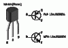
Q2&3 are TO-92 on my units. They look like this:

I'd replace that old cap you missed and new mostly MF/ and a few CF resistors and take another read with you DIM. For Phono go with MF resistors. You will have a very quite phono stage even tho the transistors on the Phono board are old school you should get decent sound. The phono board is using the -+24V from the PSU so I wouldn't sweat the -+15V which gets used by the tone control/EQ boards.

If your interest is to improve your phono section, what I did was build my own PHONO pre-pre-amp (CNC and P06) and plug it into AUX. It will blow the 17 phono away but the 17 noise floor is non-existant which is good, other than that the replacement PHONO pre-preamps I use are MUCH better sounding. The noise floor on my upgraded Phono boards are there but much lower than LP noise floor and so a non-issue.

Cheers,
Bob
 

Attachments

  • to-92.gif
    to-92.gif
    4.9 KB · Views: 16
Q2&3 are TO-92 on my units. They look like this:

I'd replace that old cap you missed and new mostly MF/ and a few CF resistors and take another read with you DIM. For Phono go with MF resistors. You will have a very quite phono stage even tho the transistors on the Phono board are old school you should get decent sound. The phono board is using the -+24V from the PSU so I wouldn't sweat the -+15V which gets used by the tone control/EQ boards.

If your interest is to improve your phono section, what I did was build my own PHONO pre-pre-amp (CNC and P06) and plug it into AUX. It will blow the 17 phono away but the 17 noise floor is non-existant which is good, other than that the replacement PHONO pre-preamps I use are MUCH better sounding. The noise floor on my upgraded Phono boards are there but much lower than LP noise floor and so a non-issue.

Cheers,
Bob


Bob,

I've been thinking of building a P06 anway because I've got a tube receiver with line level phono inputs so would require a phono preamp. I'd love to hear my turntable through it, plus it would be nice to be able to experiment with different loadings, which I think the P06 preamp allows.

On the matter of the transistor, the metal piece coming out the top looks like that of a TO-220, but without the hole in the middle to screw it to a heat sink. You wouldn't be able to screw it to anything anyway because it comes out of the middle of the top and it's too small. I'd never noticed one like that before (although that's not too surprising since I haven't messed with transistors much yet.)

I wonder what the purpose of the metal is--maybe to allow it to bleed off a little more heat than a regular TO-92 could? I took some pictures but need to find my cable to upload the pictures. As soon as I find the cable I'll post a picture.

Allan
 
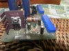
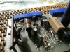
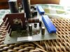
Ok, here's a couple pictures that shows the transistors I've been talking about. The first picture shows Q2 from the front. The second shows Q3 from the side. It's the one just above the middle of the picture and to the right of the very large carbon resistor.

Allan
 

Attachments

  • DSCN0136.jpg
    DSCN0136.jpg
    78.1 KB · Views: 36
  • DSCN0132 w Circle.jpg
    DSCN0132 w Circle.jpg
    88.5 KB · Views: 38
The voltage divider R9 and R10 sets the voltage on the base of Q3, which sources the voltage on pin 6. You can not get it ant more accurate unless you select the value of one of those resistors, but it doesn't have to be any more accurate than it is.
 
The voltage divider R9 and R10 sets the voltage on the base of Q3, which sources the voltage on pin 6. You can not get it ant more accurate unless you select the value of one of those resistors, but it doesn't have to be any more accurate than it is.

I mentioned replacing the CC resistors with MF. The CC resistors in "some circles" are somewhat noisy compared to MF types. I'd leave those transistors in place and swap out those carbon comp resistors and again take a test and see if that helps but as mentioned above - it's good e'nuf. Your circuit is working, tweeking for better sounds from the PSU, I'd resume re-build with MF/CF resistors. I'm listeing to my 17 right now and its all good with all inputs. Exception being the phono, the P06 or CNC beats it down, really no comparo. What TT/Cart are you using?

I've got my 17 going into tube power with QLS-3 speaks and am VERY happy with the sound. I did a total re-cap and changed all the resistors to mostly MF wth some CF in the power supply. Those big CC resistors with the socks on the legs is where I went CF. I primarily listen to LPs. You will get a VERY nice sound with this pre even with the stock pre, stick with it. The CNC and the P06 just take it to another level. If you dont try it you wont miss it and still be good with the sound.

DSTPS=dont sweat the petty stuff
DPTSS=dont pet the sweaty stuff

Cheers,
Bob
 
Dr Audio and Bob,

I've decided to let the transistors go on your recommendations and I will take on the resistors and see what happens. This all came up as a side issue while trying to troubleshoot a different problem. The other problem seems to have gone away in all the mucking about, but I'm sure it'll come back. Another learning opportunity. :-) I'm hoping I can track it down on my own, but if I have problems I'll start another thread. Thank you guys for all the help.

Allan
 
Back
Top Bottom