• The move to the new server is done. There are some software and database maintenance updates in process. This has us passing the hat around to help out. We appreciate any donations. Seriously, even a dollar helps. The payment page may be found here - https://www.audiokarma.org/support.html

Idle current adjustment of JVC A-x9 amplifier

TerryLee

New Member
The procedure of adjust idle current in service manual is as follow :

aa5.jpg - Google Drive

For the right channel, there are 5 test points (5,6,7,8,9) and the final voltage should be adjusted to 50mV.
Can anyone tell me that for the right channel which 2 points should be connected to the voltmeter to adjust to 50mV ?

Thanks very much
 
Last edited:
Register to hide this ad
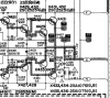
The unit has 2 sets (=4) output transistors per channel.

For the left channel measure the voltage between pins 17&20 then repeat
for pins 18&21. Best if you have 2 multimeters. Try to adjust the R513
so that both sets of readings are as close as possible and in the range
40-60mV. This will mean both sets of outputs are working near equally.
So better to have the voltages near equal, expect within 5mV.

Repeat for the right channel for pins 6&9 and 5&8. Again aim for near
equal readings, within 40-60mV range, ok to be different from the left channel

upload_2021-10-26_20-42-37.png
 
The unit has 2 sets (=4) output transistors per channel.

For the left channel measure the voltage between pins 17&20 then repeat
for pins 18&21. Best if you have 2 multimeters. Try to adjust the R513
so that both sets of readings are as close as possible and in the range
40-60mV. This will mean both sets of outputs are working near equally.
So better to have the voltages near equal, expect within 5mV.

Repeat for the right channel for pins 6&9 and 5&8. Again aim for near
equal readings, within 40-60mV range, ok to be different from the left channel

View attachment 2377273

Hello mbz, thanks for your information. According to your suggestion, is it right that the central point 7(right channel) and 19(left channel) are not being used for the adjustment process?
Moreover, I've tried to do the adjustment of right channel and has the following result sets :
(1) 5&8 20mv, 6&9 20mv when measure each point with central point 7 at this setting, it gets
7&5, 7&6 23mv
7&8, 7&9 53mv
(2) 5&8 52mv, 6&9 52mv when measure each point with central point 7 at this setting, it gets
7&5, 7&6 50mv
7&8, 7&9 102mv
From the above results, it shows that pin 5.6 are in one group and pin 8,9 are in another group. Additionally set (2) gives 52mv between 5&8, 6&9, this seems fulfil the requirement but the 102mv of pin 8,9 with pin 7 seems too high.

Could you please give furthur suggestion how should I choose the final appropriate setting?

Thanks a lot
 
is it right that the central point 7(right channel) and 19(left channel) are not being used for the adjustment process?
Points 7 & 19 are used for the central point adjustment, commonly called DC offset, It uses different adjusters to the bias adjustment.
So bias adjustment is different to DC offset adj. Forget about points 7 & 19 for bias adj, may come in handy for troubleshooting.

(1) 5&8 20mv, 6&9 20mv
While these do match they need to be in the range 40-60mV, so need to adjust R514

(2) 5&8 52mv, 6&9 52mv
I'd say that's perfect, ie the 2 sets match and they fall midway between the 40-60mV range. Don't touch.
 
Points 7 & 19 are used for the central point adjustment, commonly called DC offset, It uses different adjusters to the bias adjustment.
So bias adjustment is different to DC offset adj. Forget about points 7 & 19 for bias adj, may come in handy for troubleshooting.


While these do match they need to be in the range 40-60mV, so need to adjust R514


I'd say that's perfect, ie the 2 sets match and they fall midway between the 40-60mV range. Don't touch.

Hi mbz, I finally have the followint settings according to your suggestion :
Left channel : 17-20 50mV 18-21 49mV
Right channel : 5-8 52mV 6-9 49mV
I also set both speaker terminals to nearly 0V without loading and minimal volume.
The power consumption(100V) is around 1A and 70Watt.

Do the above settings good enough to using the amplifier normally?

Thank you very much
 
Do the above settings good enough to using the amplifier normally?
I can't give you any guarantee since I don't know the amp. The 1A/70W idle power consumption seems high however it has "Super A" bias control (whatever that is) which probably explains the 1A draw? I assume the 52mV/49mV was the best you could do. Also assume you have no test equipment like oscilloscope, signal generator, distortion analyser...If it was my amp I'd connect it to some disposable speakers and play it for a few hours at low volume making sure amp is well ventilated, listen for any distortion possibly tied to over heating.
 
I can't give you any guarantee since I don't know the amp. The 1A/70W idle power consumption seems high however it has "Super A" bias control (whatever that is) which probably explains the 1A draw? I assume the 52mV/49mV was the best you could do. Also assume you have no test equipment like oscilloscope, signal generator, distortion analyser...If it was my amp I'd connect it to some disposable speakers and play it for a few hours at low volume making sure amp is well ventilated, listen for any distortion possibly tied to over heating.

Hello mbz, I have already connected the amp to disposable speakers running for few hours and it works OK. Sound comes out in good quality without distortion, left and right channel balance is good also. Therefore, I believe that it can work well in this setting.
However, there comes out one problem is that before the adjustment, all indicators(power indicator, speaker indicator etc) in the front panel are all good can lit normally. After the adjustment, now all indicators do not work(ie. no one can lit). I think this is not the situation that one or two led bulb burns out but may be dut to control board failure or low voltage after adjustment? Do you have any idea for such case?

Thanks
 
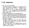
The service manual includes a description of troubleshooting lamp issues.
Appears there are 2 banks of series connected lamps,
- POWER/SPK-1/SPK-2/SUBSONIC/TONE
- REC/TAPE MON/AUX/TUNER/MM/MC

Since the lamps are in series one failure will take out others. The troubleshooting
method involves working through each switch in the bank, eg, for no power lamp,
press the SPK-1 button, does power lamp illuminate? Release SPK-1
press the SPK-2 button, does power lamp illuminate? Release SPK-2
press the SUBSONIC button, does power lamp illuminate? Release SUBSONIC
press the TONE button, does power lamp illuminate? Release TONE

When the power lamp does illuminate then the lamp corresponding to the pressed
button is faulty.

upload_2021-10-28_5-1-33.png
 
The service manual includes a description of troubleshooting lamp issues.
Appears there are 2 banks of series connected lamps,
- POWER/SPK-1/SPK-2/SUBSONIC/TONE
- REC/TAPE MON/AUX/TUNER/MM/MC

Since the lamps are in series one failure will take out others. The troubleshooting
method involves working through each switch in the bank, eg, for no power lamp,
press the SPK-1 button, does power lamp illuminate? Release SPK-1
press the SPK-2 button, does power lamp illuminate? Release SPK-2
press the SUBSONIC button, does power lamp illuminate? Release SUBSONIC
press the TONE button, does power lamp illuminate? Release TONE

When the power lamp does illuminate then the lamp corresponding to the pressed
button is faulty.

View attachment 2378550
Hello mbz, I've tried to press various buttons and found that when I press down the Tape(off) button, other lamps (power, spk-1, AUX, etc)illuminate normally. Therefore, the Tape(off) button is faulty. Moreover, when other lamps illuminate normally(eg. AUX) of the Tape(off) button being pressed down, only the Tuner lamp does not illuminate.
So I also assume the lamp of Tuner also failed.

I know that it's not possible to get the original light blub for replacement, so I want to know that can I use modern LED blub(2 - 3V) with resistor in series for replacement ? Can you recommend the combination of resistors and LED blub specification for such replacement? Thank you very much
 
Hello mbz
Where possible, best not to direct your question to specific individuals. Plenty of far more knowledgeable people on AK that would chime in and assist.

I did not see and spec on the lamps in the service manual. Remove faulty lamp and check for any voltage marking. This is the voltage that needs to be "burned" by the LED forward voltage drop Vf, typically 2.2V and the volt drop across the resistor, this consists of the LED current draw typically 40-60mA(??) x Resistor value.

Select resistor value by R = (Vlamp -Vf)/LEDcurrent, eg, assume 6V lamp then (6-2.2)/0.04 = 95ohms, round up to next value 100ohms. Check power dissipation IxIxR, eg, 0.04x0.04x100 = .0.16W so a 0.25 or 0.5W resistor will do. This is an example only.

So select the diode you like (colour, brightness etc...) then obtain diode proerties from spec sheet and calculate wanted resistor value.
 
Where possible, best not to direct your question to specific individuals. Plenty of far more knowledgeable people on AK that would chime in and assist.

I did not see and spec on the lamps in the service manual. Remove faulty lamp and check for any voltage marking. This is the voltage that needs to be "burned" by the LED forward voltage drop Vf, typically 2.2V and the volt drop across the resistor, this consists of the LED current draw typically 40-60mA(??) x Resistor value.

Select resistor value by R = (Vlamp -Vf)/LEDcurrent, eg, assume 6V lamp then (6-2.2)/0.04 = 95ohms, round up to next value 100ohms. Check power dissipation IxIxR, eg, 0.04x0.04x100 = .0.16W so a 0.25 or 0.5W resistor will do. This is an example only.

So select the diode you like (colour, brightness etc...) then obtain diode proerties from spec sheet and calculate wanted resistor value.

Thank you very much for your detail explanation. I'll try to replace faulty blub and hope that can success.
 
The unit has 2 sets (=4) output transistors per channel.

For the left channel measure the voltage between pins 17&20 then repeat
for pins 18&21. Best if you have 2 multimeters. Try to adjust the R513
so that both sets of readings are as close as possible and in the range
40-60mV. This will mean both sets of outputs are working near equally.
So better to have the voltages near equal, expect within 5mV.

Repeat for the right channel for pins 6&9 and 5&8. Again aim for near
equal readings, within 40-60mV range, ok to be different from the left channel

View attachment 2377273
Hi mbz, I just thinking of a very important question : when measure voltage between 17&20, 18&21, 5&8, 6&9 pairs,
which pin(s) shoud be connected to the +ve terminal of the multimeter ?
It's because if I measure 17&20 and connect pin 17 to +ve and 20 to -ve. When it tuned to reading of 50mV, if I
exchange the connection of +ve and -ve(ie. 17 is -ve and 20 is +ve), then the reading will become -50mv. Therefore, I need to tune the VR for 100mV until the reading is 50mV again. Obviously, there are 2 positions of the VR for the reading to be 50mV which depends on the connection of +ve and -ve pins.
Could you please explain further on this question ?
Thanks
 
Adjust for 50mV regardless of sign.

For those with OCD, connect the +ve probe to pins 20,21,5,6.
NPN transistors are base current activated so normally Vb>Ve
PNP transistors are emitter current activated so normally Ve>Vb (> = more positive)
Think of the driver transistors (X425,7) and output transistors (X431,5,,,) as a loop or "daisy chain" of current flow
into X425b (Vb approx +1.3V) out X425e (Ve=+0.7V) into X431b(Vb approx +0.7V) out X431e(Ve approx +25mV)
into X435e (Ve approx -25mV) out X435b (Vb approx -0.7)... So the emitter of NPN output (X431) will be higher/more positive
than the PNP output X435...
 
Adjust for 50mV regardless of sign.

For those with OCD, connect the +ve probe to pins 20,21,5,6.
NPN transistors are base current activated so normally Vb>Ve
PNP transistors are emitter current activated so normally Ve>Vb (> = more positive)
Think of the driver transistors (X425,7) and output transistors (X431,5,,,) as a loop or "daisy chain" of current flow
into X425b (Vb approx +1.3V) out X425e (Ve=+0.7V) into X431b(Vb approx +0.7V) out X431e(Ve approx +25mV)
into X435e (Ve approx -25mV) out X435b (Vb approx -0.7)... So the emitter of NPN output (X431) will be higher/more positive
than the PNP output X435...
Hi mbz, I've performed the adjustment of center voltage and idle current for my 2 units of A-X9 amplifiers(yes, I get 2 of it). I also have replaced failed front panel light blub with 6V 4mm incandescent blub successfully. Now both units output sound with very good quality and the power consumption is about 75W which is much smaller than the pre-adjustment value (around 110W). However, I found that both units give out sound with the right channel a little bit louder than the left channel(both units the same situation). I need to tune the balance knob to small left to get the sound balanced.
The adjustment values are as follows :
Unit 1 : 5&8 45-50mv 17&20 46-50mv
6&9 41-45mv 18&21 43-45mv

Unit 2 : 5&8 46-48mv 17&20 45-49mv
6&9 42-45mv 18&21 42-45mv

The center voltage of both units are tuned to 0V according to the service manual.

Do you have any idea about this result and anything can do to solve it?

Thanks
 
  • Like
Reactions: mbz
Those voltages look ok, they should be reasonably stable, they will change a little as the amp warms up.

The channel imbalance could be "anything", typically a dirty switch contact or solder joint or ... an oscilloscope would make life easier. As a first step try different inputs like connecting CDP (or whatever) to TUNER then compare to AUX. Also try PHONO.
Also try moving speakers to the second set of connectors at rear (set B or 2), also try working through all switches tone, bass, treble,,, move switch several times noting any change in the balance, good or bad
 
Back
Top Bottom