• The move to the new server is done. There are some software and database maintenance updates in process. This has us passing the hat around to help out. We appreciate any donations. Seriously, even a dollar helps. The payment page may be found here - https://www.audiokarma.org/support.html

IMF Transmission Line Stuffing?

The real transmission line speaker loading

There is NO "fantasy or magic" about the A.R. Bailey transmission line design. Bailey understood audio engineering and had good ears. He developed the design experimentally (some may say by trial and error) by measuring different fiber materials. His methodology is thorough and impeccable. His effort can be easily duplicated using the same fiber material he recommended. I am one of those who tried and convinced. Bailey showed the performance of a commercial system in his article and that was very impressive.

20 years later, Gary Galo was able to build and measure transmission line speakers filled with long fiber wool. He showed that everything worked as Bailey described. Gary was NOT a good analyst. Martin King can attach his writing on the theory part, but there was nothing fundamentally wrong with his creation and the measurements he made.

L.J.S. Bradbury at University of Surrey was familiar with the sound absorption researches done for submarine application during the 1940's and 1950's. He applied the same analytical and experimental technique to the design of transmission line speaker and wrote an execellent paper about the results in 1976. He confirmed that long fiber wool is REQUIRED for proper working of a transmission line and showed both analytical and experimental evidence for his results.

But the linear algebra model of the fiber filled line does not lean itself to easy integration with the Thiel-Small filter model of speaker drivers. Both the Bradbury model and the Thiel-Small model are wonderful piece of engineering work. Someday, someone may create a combined model to predict transmission line speaker performance. (But not by throwing out the effect of long fiber wool stuffed tube the way that George Augspurger or Martin King did. They both showed that polyester fiber did not work for TL.)

It is offensive for someone to call the solid engineering works of Bailey and Bradbury "religion", "fantasy and magic", without ever bothering to build and test a long fiber wool stuffed transmission line. I will challenge anyone who made those statement to point out specific technical error, if any, in the Bailey and Bradbury papers.
 
Fried had an anechoic room when he was on City Line Avenue in Philadelphia.
This is where he tested and let his prospective customers audition his designs.

If one measures the impedance at the woofer terminals the truth of the enclosure being a non resonant enclosure or a helmholtz resonator is revealed.
Having a flat impedance is one advantage of a non resonant enclosure being easier for amps to drive.

I found impedance peaks substituting fiberglass in the C3L enclosures.
I have built quite a few clones using substitute drivers in the C3L enclosures that measured flat in their response.

IIRC I have built 14 T-line enclosures since the mid 1980's.
 

Attachments

  • DSC_0075.jpg
    DSC_0075.jpg
    70.7 KB · Views: 133
It is offensive for someone to call the solid engineering works of Bailey and Bradbury "religion", "fantasy and magic", without ever bothering to build and test a long fiber wool stuffed transmission line. I will challenge anyone who made those statement to point out specific technical error, if any, in the Bailey and Bradbury papers.

I made direct comparisons of long fiber wool and polyester and found the differences were minimal after measuring electrical impedance and acoustic output. Have you done the same?

See Post #50 for the error made by Bradbury.
 
Fried had an anechoic room when he was on City Line Avenue in Philadelphia.
This is where he tested and let his prospective customers audition his designs.

If one measures the impedance at the woofer terminals the truth of the enclosure being a non resonant enclosure or a helmholtz resonator is revealed.
Having a flat impedance is one advantage of a non resonant enclosure being easier for amps to drive.

I found impedance peaks substituting fiberglass in the C3L enclosures.
I have built quite a few clones using substitute drivers in the C3L enclosures that measured flat in their response.

IIRC I have built 14 T-line enclosures since the mid 1980's.

Have you designed one yourself, building a clone does not count, and predicted the electrical impedance and SPL output both empty and stuffed? Then have you measured the results and checked the correlation? Can you provide plots like I did earlier in the thread? Building somebody else's design and having it sound good is fine but does not demonstrate knowledge of what is important in the design of a TL.
 
]
attachment.php
Have you designed one yourself, building a clone does not count, and predicted the electrical impedance and SPL output both empty and stuffed? Then have you measured the results and checked the correlation? Can you provide plots like I did earlier in the thread? Building somebody else's design and having it sound good is fine but does not demonstrate knowledge of what is important in the design of a TL.

Yes the photo in post #122 is one of the DIY designs I have built using an 8" Dalesford D100/200 and 3/4" dome tweeter. I have followed the Fried design parameters with all of these designs.

attachment.php

I have built several using buy out drivers I have purchased over the years.
The Bose 201 6.5" drivers that were 3.95$ a piece measure flat to 60hz in a 4 foot long line.

attachment.php

I have used Zalytron Carboneau and Audax HD17, HD21 bextrene cones in several DIY designs..

I found the Sony cube drivers that have a Fs of 270hz measured flat using a line length of 18" at 300hz.

attachment.php

I found using the cube drivers in a 1/4W T-line did cause increased cone excursion compared to use in a closed box design but did sound more natural.
The sub below the cube driver T-lines use a pair of Audax HD17B37R2C12 in a 4.5ft T-line.
I also have T-lines under the back seat of my truck that use Fried C6 oem drivers in a DIY design.
 
Keilau back when I started to subscribe to Speaker Builder around 1992 I purchased all the back issues available.
The 1985 and 1989 issues were sadly not available.

I also have experience with the Audax HD24B45 with T-line enclosures that Gary A. Galo used in his TL-10 design.
A friend of mine built a T-line with the Audax 10" using plans from one of the DIY vendors around 1981-82. I do not remember the vendor.
Too make a long story short he was not satisfied with the results.
I believe wool was used in this design. I also remember the free flow of air in the design at line terminus was far less then the Fried design using foam.
There wasn't much of a taper ratio in this design either.

He later built a Fried O1 T-line clone. We measured the value of the air core coil Fried used which is a 12mh 14 gauge air core inductor.
We compared both designs using the Fried sub crossover and settled with using the Fried design.
The Audax driver did have limited spl due to the short xmax of 3mm but the low bass was definitely there using the Fried O1 design.

I have enclosed a photo of Ohighway's Fried O2 subs which is the same T-line enclosure as the original O1 model.

http://www.audiokarma.org/forums/attachment.php?attachmentid=412838&d=1361818508
 
I made direct comparisons of long fiber wool and polyester and found the differences were minimal after measuring electrical impedance and acoustic output. Have you done the same?

No, I have not done the same comparison. I have never imagined building a transmission line speaker NOT using long fiber wool for stuffing. The only TL speakers I built was the Bailey 1972 design. They were stuffed with long fiber wool that meets the specification from Bailey and Bradbury. I did take measurement of these speakers.

AD10100-bailey.jpg AD10100-KO040.jpg

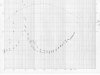
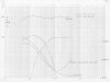
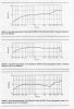
I used the El Cheapo Phillips AD-10100 10" paper cone woofers. The result was extremely good considered the price of the drivers. You can see the bass has a -6 dB point at 45 Hz and -12 dB at 20 Hz. No, this is not nearly as good as the Bailey result using the KEF BD-139 drive. But the low end reach is far beyond one could expect using the same drive in a close box. More importantly, it has a slow decay curve or 6 dB/octave to couple with the low end. The total result is a very low, very tight bass using a low cost 10" driver.

You can also see that the impedance had a single bump. The driver has a free air resonant frequency, Fs, of 35 Hz. I expect the system (transmission line plus driver) to be close to that and it was at 46 Hz. The result was higher than I expected. I attribute it to the fact that Phillips AD-10100 was a good TL driver, but not as good as more ideal one such as the KEF. (JimPA, now you know why I always want to try the BD-139.)

This was the mid 1970's. So the results were plotted on semi-log paper manually. Hey, it is before the Windows PC time.

The result convinced me that Bailey and Bradbury had hit the jackpot. In their papers, you would see that other kind of fiber does not produce the same result. My characteristics of the transmission line speakers I built is very similar to those published by Bailey and Gary Galo.

response_Bailey-1965-Non-resonant-Loudspeaker-Enclosure-Design.jpg Galo-TL10.jpg

I will like to see Martin King post his result using 10" driver here and compare them to those I post above.

See Post #50 for the error made by Bradbury.

Bradbury did not made the error you said because he never made the statement you attributed to him. In fact, it was to the contrary.

In the Bailey and Bradbury design, the fiber used are heavy (high density) and mechanically stiff so that they will not move in the acoustic wave. By not moving, the fiber create form drag (also called pressure drag which is different from viscous drag) to slow down the air and resulted in a effectively longer acoustic line. But it will not attenuate the acoustic energy at the lower frequency. By acting as a phase inverter near the Fs of the driver, the back wave comes out from the line terminus to reinforce the front wave.

Martin King saw the air velocity and fiber velocity terms in Bradbury's formulation. But he did not read the details in the paper to understand that the fiber velocity was supposed to be negligible for the TL design to work. Martin King kept saying that the air and fiber move together, which is exactly opposite to what Bailey and Bradbury concluded. The open cell foam that Bud Fried used works well in transmission line speaker because it will not move with the air too and can create an equivalent acoustic line that is longer than the actual physical length while passing through the low frequency energy.

Martin King can keep saying the Bailey TL theory to be "fantasy and magic" and "religion". But it was shown repeatedly working. The so called Martin King "modern transmission line" was never shown to work the way Bailey intended.
 
I attribute it to the fact that Phillips AD-10100 was a good TL driver, but not as good as more ideal one such as the KEF. (JimPA, now you know why I always want to try the BD-139.)

Keilau I am long time customer of Fried and live in very close proximity to where he once resided in Gladwyne, PA.

Fried had used the Kef B139 in his first model R speaker.

Fried gave up with the Kef drivers and had his TOTL drivers all custom made to fit his design parameters.

Voice coil burnout was one of the main problems from being over driven and bottoming out on the low bass passages in music
Fried didn't like the heavy cone mass of the Kef drivers and short xmax.
The oem drivers he had designed could play around 8-10 db louder and the costs were much higher to manufacture than the Kef drivers.
Fried first used Bextrene cones that were thinner then what Kef and Audax used. Fried had a larger amount of plastiflex applied to the cones to dampen them.

I never took any photos of my 10" Fried Dalesfords but there is a photo on another website of one of his oem versions similar to mine.

https://sites.google.com/site/mpbarneyspeakers/friedmodeltsubwoofer

The specs on the stock Dalesford drivers on that site are off quite a bit.
The gentlemen who occasionally posts on this site has verified this.
He use to be the sole USA importer of those drivers to all the USA vendors.

Fried developed quite few high performance drivers designed for his T-line designs.

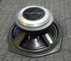
The driver on the left is the Fried Gefco 6.5" composite cone.
The pulp paper cone incorporates wool, kevlar and carbon fiber and has a thick butyl rubber surround.

The driver on the right is the last Fried Dalesford 6.5" bextrene cone with a PVC surround.
Fried used this version in the first model C aperiodic design sold for professional monitoring applications.
I use one pair in my C3L enclosures.

BTW that is my son in the background preparing his meal.

attachment.php


This is a photo of the Gefco 10" composite cones that were used in the O6 sub woofer.
attachment.php


As you can see I have a wide variety of oem Fried drivers developed for their intended use. :)
 

Attachments

  • $T2eC16N,!ykE9s7tvVlOBRPp2G(nWQ~~60_57.jpg
    $T2eC16N,!ykE9s7tvVlOBRPp2G(nWQ~~60_57.jpg
    109.2 KB · Views: 29
JimPA,

You are a treasure of information on the transmission line speakers and an invaluable asset to the DIY community.

I am just a hobbyist who built one pair of TL speakers and like it. Thank you for sharing the information.
 
JimPA,

You are a treasure of information on the transmission line speakers and an invaluable asset to the DIY community.
.

Keilau thanks for the compliment.
There are many knowledgeable members on the forum that my might beg to differ with you.

I do value your insight and respect your findings due to your engineering background.
 
Other than Bailey and Bradbury, are there published data on different stuffing materials using the same cabinet and measurement method?

Result of Long fiber wool vs. fiber glass vs. polyfill vs. open cell foam?

With the physical characteristics of the stuffing materials properly documented. It may be difficult to make line terminus amplitude and phase measurement. But simple summed frequency response of the whole system and impedance curve would be very helpful.

A. R. Bailey published his "A Non-resonant Loudspeaker Enclosure Design" in October, 1965. It is 49 years. (No tuning is possible since the design is Non-resonant.) :nono:

Anyone has measured a polyester fiber stuffed transmission line in comparison with a long fiber wool filled one? Can you show your response and impedance curves?
 
A bass reflex speaker is a second order system that mates a resonant driver to a resonant cabinet where the air in the port acts as the mass and the air in the box acts as the spring. These two resonant systems are put together and produce a second order system that hopefully produces a flat SPL above the tuning frequency, has a knee that is fairly sudden, and then quickly transitions to a 24 dB/octave roll off below the tuning frequency.

A bass reflex or port vented system is 4th order, not second order, and yes, like all 4th order high pass filters they roll off at 24dB/oct.
This is why T&S theory refers to a Butterworth vented alignment as B4, and a Chebyshev as C4, and there are obviously many, many others.
A vented system plus a 2nd order boost high pass filter is 6th order, B6 or C6 in T&S theory.
A sealed Butterworth alignment is second order and referred to as B2 in T&S theory. They rolloff at 12 dB/oct.

There is no speaker that rolls off at 6 dB/oct as Keilau has been claiming.
 
A bass reflex or port vented system is 4th order, not second order, and yes, like all 4th order high pass filters they roll off at 24dB/oct.
This is why T&S theory refers to a Butterworth vented alignment as B4, and a Chebyshev as C4, and there are obviously many, many others.
A vented system plus a 2nd order boost high pass filter is 6th order, B6 or C6 in T&S theory.
A sealed Butterworth alignment is second order and referred to as B2 in T&S theory. They rolloff at 12 dB/oct.

There is no speaker that rolls off at 6 dB/oct as Keilau has been claiming.

Pete,

Post 71 corrected my mistake, typing faster than thinking got me agian.

Martin
 
HI, I own a pair of IMF prof. Mk III (fill with fiberglass) and tTls 50 with a yellow beige inside the cabinet, the foam mostly in top , behind woofer 3 blocks of foam with space in between, top of mid tube block of foam with space all arround, end of T-line grey foam twisted ,middle of t-line ? Probably a bit of foam, but just to say I'm no expert, it seems when you look simply to it, the back wave,pressure,air flow? Call it whatever you want, and the foam absorb some of it,eliminate any resonance, maybe help build-up behind the woofer and dissipate along the T-line, the t-line is not fill completely like Mr.Bailey or like wave go true to an air filter, I hope you understand what I try to say, I'm not a Wizards and not good at all with formula and calculation,best regards, Yvan
 
Here is some good reading to understand the effect of using low density polyurethane foam in transmission line enclosures.

The tests done by Delany and Bazley in 1970 shows how the speed of sound is changed when sound travels through porous materials.
I have enclosed the studies done by others on the properties of acoustic absorption materials.
There were numerous studies done and some are in pdf form which are too large upload to a thread.

When it comes to a stuffing material it comes down to the air flow resistivity of the material used in the lines.
I find it interesting how some of the tests were done with wind tunnels.


DelanyBazleyModel.html
15_chapter 2.pdf
20110011143.pdf
BeBeC-2012-05.pdf
665968-sound-speed-porous-absorbers.html
Sound-absorption-Thermal-and-Mechanical-behavior-of-Polyurethane-foam-modified-with-Nano-silica.pdf
 
Back
Top Bottom