

You are using an out of date browser. It may not display this or other websites correctly.
You should upgrade or use an alternative browser.
You should upgrade or use an alternative browser.
In Need of SA-7800 Schematic
- Thread starter greap666
- Start date

Ok, I don't remember what state the amp was in, if there are removed transistors, replaced transistors etc...
Sorry I didn't see this sooner. If I miss your post while we are troubleshooting, (by checking my last post time /date..) PM me to "wake me up" so to speak.
The first thing to check, if the amp is together, is the dc offset at the outputs, before they reach the relay and are disconnected from the speaker terminals.
Since the protection relay is on the p.c. board, the middle row of terminals on the protection relay (there are 4 terminals in the top row, 4 terminals in the middle row and only 2 terminals in the bottom row) are the connections we seek. Two are one channel, and two are the other.
This thread discusses the test and the interpretation of the results.
BUT if the voltages are greater than about 100 millivolts (positive OR negative), the protection circuit will not allow the speakers to be connected.
Sorry I didn't see this sooner. If I miss your post while we are troubleshooting, (by checking my last post time /date..) PM me to "wake me up" so to speak.
The first thing to check, if the amp is together, is the dc offset at the outputs, before they reach the relay and are disconnected from the speaker terminals.
Since the protection relay is on the p.c. board, the middle row of terminals on the protection relay (there are 4 terminals in the top row, 4 terminals in the middle row and only 2 terminals in the bottom row) are the connections we seek. Two are one channel, and two are the other.
This thread discusses the test and the interpretation of the results.
BUT if the voltages are greater than about 100 millivolts (positive OR negative), the protection circuit will not allow the speakers to be connected.


greap666
Active Member
Just woke up it's 03:11 EST. I think I'll give it a run in the morning. Thanks for all of your help. I have read the thread on DC offset and understand what to do.
Mark...the condition of the amp when we started was smoking resistors, fried resistors. I had to replace R54 (220), R60 (150 1/2 watt) and R36 (560). I still need to replace R34 with only one resistor, currently a double resistor configuration was used by previous tech to acheive the value comparable to the one that failed and was replaced at R60. It seems to be ok but would rather replace it while I'm in here.
Oh by the way, I don't know if you read earlier in this thread about the markings on the caps I found but instead of guessing on these I'm just going to replace them. Hopefully the Nichicon 100uf 50v arrive tomorrow then I could get on with this. Also a 470uf 25v on the equalizer board has to be replaced. Not bulging or leaking just would feel much better.
Just to let you know, there are many and I mean many repairs done to this as indicated by new solder joints. They were done very cleanly. The transistors that you mentioned I should check Q26 and Q4 were amongst the repaired but I still may need to look again at those.
Anyway I need some sleep.
Thanks again. :thmbsp:
Mark...the condition of the amp when we started was smoking resistors, fried resistors. I had to replace R54 (220), R60 (150 1/2 watt) and R36 (560). I still need to replace R34 with only one resistor, currently a double resistor configuration was used by previous tech to acheive the value comparable to the one that failed and was replaced at R60. It seems to be ok but would rather replace it while I'm in here.
Oh by the way, I don't know if you read earlier in this thread about the markings on the caps I found but instead of guessing on these I'm just going to replace them. Hopefully the Nichicon 100uf 50v arrive tomorrow then I could get on with this. Also a 470uf 25v on the equalizer board has to be replaced. Not bulging or leaking just would feel much better.
Just to let you know, there are many and I mean many repairs done to this as indicated by new solder joints. They were done very cleanly. The transistors that you mentioned I should check Q26 and Q4 were amongst the repaired but I still may need to look again at those.
Anyway I need some sleep.
Thanks again. :thmbsp:
That's a pretty nasty path of destruction, BTW those resistors are in ohms, the symbol k denotes 1000's of ohms. It's kinda hard to blow up a 560,000 ohm resistor, especially with the voltages available in the sa-7800.
I would carefully check Q16 and Q18 also.
R60 is the emitter resistor for Q26, while R54 is the base resistor for Q26.
One side of R36 is connected to R54, so the blast somehow came through Q16 or Q18, all part of the bias? circuit.
If R42 is ok (check it too) check VR6, that blast had to pass through somewhere...
I would carefully check Q16 and Q18 also.
R60 is the emitter resistor for Q26, while R54 is the base resistor for Q26.
One side of R36 is connected to R54, so the blast somehow came through Q16 or Q18, all part of the bias? circuit.
If R42 is ok (check it too) check VR6, that blast had to pass through somewhere...
greap666
Active Member
markthefixer said:That's a pretty nasty path of destruction, BTW those resistors are in ohms, the symbol k denotes 1000's of ohms. It's kinda hard to blow up a 560,000 ohm resistor, especially with the voltages available in the sa-7800.
I would carefully check Q16 and Q18 also.
R60 is the emitter resistor for Q26, while R54 is the base resistor for Q26.
One side of R36 is connected to R54, so the blast somehow came through Q16 or Q18, all part of the bias? circuit.
If R42 is ok (check it too) check VR6, that blast had to pass through somewhere...
You'll have to excuse me for the "k" symbol, it was 3:11 am

Anyway I'm back at it got a day off today. Should I check the DC offset or continue to pull the items you suggested? :scratch2:
Thanks.
greap666
Active Member
greap666 said:As I mentioned earlier there was alot of resoldering done. Looks to me like the previous tech took off all of the transistors and checked them then reinstalled them.
There also is a "913" notation on the chasis obviously refering to 2SA913.
R42 is fine reading 100.5
greap666
Active Member
C26 And C11
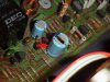
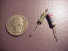
Here's images of the two caps that I mentioned earlier in this thread in reference to black and green markings. As I said I don't know if there is any meaning behind them
Since these are large images I will be taking them down after you see them.
Thanks.
Here's images of the two caps that I mentioned earlier in this thread in reference to black and green markings. As I said I don't know if there is any meaning behind them
Since these are large images I will be taking them down after you see them.
Thanks.
Attachments

greap666
Active Member
The cap markings ment something to somebody, but that meaning is long lost.
Before adding power I would have checked VR6 to make sure it is ok. BUT since you have turned the power on already, if anything bad was going to happen, it did.
Read the offset voltages, as per the quoted thread, at the relay, if you can reach those connections, otherwise, you have the manual, use the pc layout to find some points on the board where there is a direct connection. IIRC there should be several.
The rest of the suggestions were for when the readings you make show a problem with an amplifier channel as opposed to a defective protection circuit.
The schematic does list voltages that should be found at various points, and you probably have one channel that is working.
BUT in the spirit of good troubleshooting, I think we should make a quick check of the power supply voltages, first. It's very frustrating to chase a problem that is caused by something so easily checked.
ON the power supply board, (gwr-114?) the wires leaving the board are numbered,
15,16,17 are +48volts
19,20,21 are -48volts
29,30 are +46volts
31,32 are -46 volts
Before adding power I would have checked VR6 to make sure it is ok. BUT since you have turned the power on already, if anything bad was going to happen, it did.
Read the offset voltages, as per the quoted thread, at the relay, if you can reach those connections, otherwise, you have the manual, use the pc layout to find some points on the board where there is a direct connection. IIRC there should be several.
The rest of the suggestions were for when the readings you make show a problem with an amplifier channel as opposed to a defective protection circuit.
The schematic does list voltages that should be found at various points, and you probably have one channel that is working.
BUT in the spirit of good troubleshooting, I think we should make a quick check of the power supply voltages, first. It's very frustrating to chase a problem that is caused by something so easily checked.
ON the power supply board, (gwr-114?) the wires leaving the board are numbered,
15,16,17 are +48volts
19,20,21 are -48volts
29,30 are +46volts
31,32 are -46 volts
greap666
Active Member
markthefixer said:The cap markings ment something to somebody, but that meaning is long lost.
Before adding power I would have checked VR6 to make sure it is ok. BUT since you have turned the power on already, if anything bad was going to happen, it did.
Read the offset voltages, as per the quoted thread, at the relay, if you can reach those connections, otherwise, you have the manual, use the pc layout to find some points on the board where there is a direct connection. IIRC there should be several.
The rest of the suggestions were for when the readings you make show a problem with an amplifier channel as opposed to a defective protection circuit.
The schematic does list voltages that should be found at various points, and you probably have one channel that is working.
BUT in the spirit of good troubleshooting, I think we should make a quick check of the power supply voltages, first. It's very frustrating to chase a problem that is caused by something so easily checked.
ON the power supply board, (gwr-114?) the wires leaving the board are numbered,
15,16,17 are +48volts
19,20,21 are -48volts
29,30 are +46volts
31,32 are -46 volts
That would be GWR-112 Power Supply Ass'y
greap666 said:I was reading the thread earlier on adjusting the DC offset and was wondering could this be what happened to this amp or something similar where it was not done properly?
Just a thought..... :scratch2:
It's only a remote possibility, if the amp is wayyy out to start with, then the adjustment skews it just far enough..
The power supply voltages are fine, what are the offset voltages? Can you get to the underside of the board with the relay to measure them there, or can you find another directly connected point using the manual.
Otherwise a picture of the board with the relay is indicated, where I will trace it using the manual and re-post with points to read indicated.
two threads today have converged, both are in about the same functional area of different amps (sx-828 and sa-7800)..... my notes have converged and my head is starting to spin....... :stupid:

greap666
Active Member
markthefixer said:It's only a remote possibility, if the amp is wayyy out to start with, then the adjustment skews it just far enough..
The power supply voltages are fine, what are the offset voltages? Can you get to the underside of the board with the relay to measure them there, or can you find another directly connected point using the manual.
Otherwise a picture of the board with the relay is indicated, where I will trace it using the manual and re-post with points to read indicated.
two threads today have converged, both are in about the same functional area of different amps (sx-828 and sa-7800)..... my notes have converged and my head is starting to spin....... :stupid:
Which board do you need to see an image of?
greap666
Active Member
greap666 said:Which board do you need to see an image of?
Sounds like a well deserved break is in order. :beer:
Thanks again. :thmbsp:
greap666 said:Sounds like a well deserved break is in order. :beer:
Thanks again. :thmbsp:
JUst got back on, if you can't measure at the back of the relay, the picture should show the component side of the long thin board with the relay in the center of it. It is in the second picture you attached to post #30.
The manual shows the foil side of the board, and I have 2 chances out of 3 to screw up the locations of where to probe. A picture gives us a common point of reference.
That was a bit of a toungue in cheek statement, I'm not any more ready for the loony bin than I usually am.......
wild weather here Hail etc, gutters finally doing their job (somewhat).
This one:
greap666
Active Member
markthefixer said:JUst got back on, if you can't measure at the back of the relay, the picture should show the component side of the long thin board with the relay in the center of it. It is in the second picture you attached to post #30.
The manual shows the foil side of the board, and I have 2 chances out of 3 to screw up the locations of where to probe. A picture gives us a common point of reference.
That was a bit of a toungue in cheek statement, I'm not any more ready for the loony bin than I usually am.......
wild weather here Hail etc, gutters finally doing their job (somewhat).
This one:

Two images on the way to you via email wide angle and zoomed in of Power Amp Assembly