• The move to the new server is done. There are some software and database maintenance updates in process. This has us passing the hat around to help out. We appreciate any donations. Seriously, even a dollar helps. The payment page may be found here - https://www.audiokarma.org/support.html

In search of audio mute relay (Crown)

Stalmer

Member
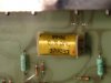
My Crown SL-1 preamp has an apparent issue with the audio mute relay. Any suggestions for finding a replacement? I have no idea if this was made specifically for this unit or if it was mfctd for other units or companies. I do know that Crown no longer supports the vintage stuff from the 70s and 80s. If all else fails, I guess I can bypass and simply turn the amp on separately from the preamp to protect the speakers from thumps (on and off). Image attached.

 

Attachments

  • Crown relay - reduced.jpg
    Crown relay - reduced.jpg
    48.5 KB · Views: 17
Register to hide this ad
See if you can figure out how to measure the relay coil resistance. Also measure the coil voltage. Or if you have a schematic or SM that will tell you the coil voltage.
 
There are hundreds of reed relays . With a little wiring. And a little glue or epoxy. Its easy to sub a new relay in that will work as it should.
 
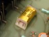
Shoot a pin out shot? Not sure what you mean. You mean a side view showing pins?
 

Attachments

  • Crown relay 2.jpg
    Crown relay 2.jpg
    42.7 KB · Views: 7
Yeah, as far as measuring the coil, it's not really clear how to go about it (where to put the probes). I have a schematic, however.
 
In you photo. Those two centered pins are the relay contacts. The pin closest to the side of the relay is a coil connection. The other coil pin is closest to the same side at the other end.
 
Clip your Neg. test probe to chassis ground. Use the Pos. test lead to probe DC voltages. Never touch more than one testing point at a time. Maybe wrap a little electrical tape or use a bit of heatshrink tubing to insulate 95% of the metal probe tip. Leaving the probe point exposed. With power applied measure for DC voltage at both coil leads (one at a time). Or find the relay in the schematic and follow the coil leads connection back to the power supply. Hopefully your schematic has some expected voltages printed in the schematic along the path to the power supply. I'm guessing 12 vdc. :idea:
Then disconnect power. With you meter and both test leads measure the resistance between the coil leads. Need this resistance value to select a suitable replacement reed relay.
 
Back
Top Bottom