

JayWFletcher
New Member
Hello,
I'm hoping someone can help me debug some problems that have come up after I recapped a KA-6100 integrated amp. There appears to be a short somewhere so I am running the amp on a DBT to prevent the fuses from blowing. I have double/triple/quadruple checked the polarity of all of the electrolytic caps, checked for cold solder joints, checked for bridged traces, and everything looks OK.
I have gone through the schematic and checked voltages at all of the transistors and found some issues. For brevity I have only listed the checks I made from the rectifier diodes through the main power amp section below (still a lot, sorry). The voltage at Rm131/Rm132/D20 is 0.64, just too low to make the relay close.
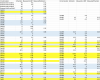
I hope this table of measurements will be helpful. I have highlighted the discrepancies between the schematic and measured voltages in yellow. The nominal voltages are all about 1/10 of normal due to the DBT.
I realize that I should have fixed the amp before I installed new capacitors, but that horse has left the barn. I'm an engineer, but not an electrical engineer, so I can read a schematic, but I don't have a feel for how these circuits work. I can use a DMM and I know how to do a 6-way check on transistors. I have verified that all of the transistors shown below are good by removing them from the circuit and doing a 6-way check.
Thanks in advance for any help you can provide.
Jay

I'm hoping someone can help me debug some problems that have come up after I recapped a KA-6100 integrated amp. There appears to be a short somewhere so I am running the amp on a DBT to prevent the fuses from blowing. I have double/triple/quadruple checked the polarity of all of the electrolytic caps, checked for cold solder joints, checked for bridged traces, and everything looks OK.
I have gone through the schematic and checked voltages at all of the transistors and found some issues. For brevity I have only listed the checks I made from the rectifier diodes through the main power amp section below (still a lot, sorry). The voltage at Rm131/Rm132/D20 is 0.64, just too low to make the relay close.
I hope this table of measurements will be helpful. I have highlighted the discrepancies between the schematic and measured voltages in yellow. The nominal voltages are all about 1/10 of normal due to the DBT.
I realize that I should have fixed the amp before I installed new capacitors, but that horse has left the barn. I'm an engineer, but not an electrical engineer, so I can read a schematic, but I don't have a feel for how these circuits work. I can use a DMM and I know how to do a 6-way check on transistors. I have verified that all of the transistors shown below are good by removing them from the circuit and doing a 6-way check.
Thanks in advance for any help you can provide.
Jay
Last edited:
