• The move to the new server is done. There are some software and database maintenance updates in process. This has us passing the hat around to help out. We appreciate any donations. Seriously, even a dollar helps. The payment page may be found here - https://www.audiokarma.org/support.html

Increasing Power Supply Capacitance, Fisher SA300

perchdog

AudioDouchebag
I am looking for advice... I have a Fisher SA300B that I would like to rebuild, I want to do in stages and start with the power supply.

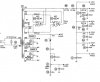
I was wondering where it would be a good idea to either add or increase capacitance, and would anything else need to change (ie resistor values). Attached are pdf's of the schematic and parts list per Sam's service manual.

Any recommendations

PS, Moderators, I posted here on purpose for more exposure, if thread is to be moved to Fisher forum, can we let it stew for a bit first
 

Attachments

Register to hide this ad
I've got an SA-300, so I'm also curious, but I think the first stop is possibly looking into putting in a choke. Sizing and getting it to play nice would require some work.

Also, Fisher didn't size their power supplies incorrectly for what they intended their power supplies to do.
What might make sense is to consider dcgillespie's EFB mod. That's what I'd like to do anyway. That might provide far more power than adding power supply capacitor storage. There are a couple of 5AR4s to think of too and adding capacitance to the power supply without calculating risk/benefit may prove expensive.
I say that without looking though.
Let the gnashing begin!
 
The big question is DO You want it still to be a Fisher SA300 when your done , or do you want to do it with a seperate power supply .

This amp uses Cathode bias and fixed bias , so a EFB would not be a sraight forward propasision .

This amp screams for a bigger chassis to work with .
 
The big question is DO You want it still to be a Fisher SA300 when your done , or do you want to do it with a seperate power supply .

This amp uses Cathode bias and fixed bias , so a EFB would not be a sraight forward propasision .

This amp screams for a bigger chassis to work with .

I do agree the chassis is quite busy, I would like to keep everything on it though
 
I was wondering where it would be a good idea to either add or increase capacitance,

I'd keep C1 the same value, 60uF, but you can increase the capacitence values of the other cpas in the power supply. The reason to not increase C1 is that more capacitence right next (electrically) to the rectifier tubes will increase the peak current, and tube rectifiers get real unhappy with excessive peak current. The otehr caps are buffered by at least 600 ohms, and thus won't increase the peak current the tube rectifiers would see. 30 ohms is not enough of a buffer. You can use higher voltage rated caps in all positions, and not have a problem, though.
 
I've got an SA-300, so I'm also curious, but I think the first stop is possibly looking into putting in a choke. Sizing and getting it to play nice would require some work.

Also, Fisher didn't size their power supplies incorrectly for what they intended their power supplies to do.
What might make sense is to consider dcgillespie's EFB mod. That's what I'd like to do anyway. That might provide far more power than adding power supply capacitor storage. There are a couple of 5AR4s to think of too and adding capacitance to the power supply without calculating risk/benefit may prove expensive.
I say that without looking though.
Let the gnashing begin!

This post brings up a question that I only get debates on. If you run two rectifiers in parallel, can you then double the input cap uf rating? If so, two 5AR4s would allow for 100uf right, but I've been told by what I believe to be knowledgeable folks that it's not that simple. I've also been told by people I believe to be knowledgeable that it is exactly that simple. Whenever faced with dual tube rectifiers I always wire each one to it's own cap even though they end up together anyhow. I wish I could see for sure if this rating doubles in an RCA manual or something.
 
One thing I've found works nicely in tube rectified PSs is to use a poly cap after the tube rectifier. That way you can stay at the same uF value but get far better filtering than with an electrolytic. :yes:
 
Good question. The only thing I own with dual rectifiers has them set up as a pair of half-waves fed into I think a 20 or 40 uf cap. Its not real big, whatever it is. Rectifiers are a pair of 5Y3, and its not pushing the limits on it at all. Perhaps thats why they are original from 1947. They simply loaf along in there.

can't help but think you'd get better results ditching those two 15 ohm resistors for a choke, if space permitted. In the past I've found that adding a resistor between the rectifier and the first cap makes things a bit less well regulated than having no resistor and a smaller first cap. Something to do with lower power supply impedance I guess. At one time I had a 100 ohm and a 470uf first filter cap in my Magnavox. It actually works better with no resistor and a 47uf cap.
 
Last edited:
I like that approach wa2ise.

How about a normal power supply string, say 40uf to R and 40uf, to R and 33 uf, to R then 200uf for the last cap which feeds the phono section power supply. Think about this for awhile, I'm curious to hear thoughts on it.

Say the inverter driver stage runs out of gas a bit on a huge bass note. Will it "steal" power from the 200uf phono supply cap? If so, what are the negatives. How about a diode leaving each PS node then feeding it's stage. Wouldn't that give you better de-coupling. Just random goofy thoughts.:scratch2:
 
One thing I've found works nicely in tube rectified PSs is to use a poly cap after the tube rectifier. That way you can stay at the same uF value but get far better filtering than with an electrolytic. :yes:

If you have room, I think it's Mouser that sells a nice little blue square one rated at 10uf or 15uf and 600vdc. Maybe 1/3rd the size of a pack of smokes.
 
I looked at my Fisher schematic and, honestly, schematics never speak to me. I just looked at the enclosed SAMS and that makes more sense than the official Fisher schematic.
Then I looked at the schematic for the power supply to my Fisher X-1000, which seems to use a diode bridge to do what these two rectifiers are doing.

Fisher X-1000 diode bridge:
attachment.php


Fisher SA-300 rectifiers according to SAMS:
attachment.php


I think there's been a lot of useful feedback and comments.
Battradio's comment about do we still want it to be an SA-300-B?
For these, yes. At least for me, if I could find a choke that could replace those two 15 ohm resistors, that bolts under the chassis, I'd try it, but I also doubt it.
This amp was made to sit in the back of a console. The official Fisher schematic is part of a Fisher President VIII service manual.
There seem to be a lot of big power resistors in this amp though.
Recently there was an SA-300 on BT that was beat. If I knew my chops better, then the answer to Battradio would be no and I'd hunt for a chassis that could support a redesign and include a respectable choke.

To Gadget's comment about does each rectifier do one half, I don't have the bench free at the moment to look and test with a scope, but I'm guessing yes. Why else would they each go to a tap off the primary, with one using pin 2 to go to the tap and one using pin 8 to go to the tap?

To Jay, did you find any benefit from using one cap to each rectifier? If each is doing a half wave thing, what benefit would splitting the cap up offer? I can see why you've never gotten a straight answer though. Could it be that in 1958/9 they didn't have beefy enough SS diodes so they used rectifiers in a diode bridge, but they did have beefy enough ones in '61 when the Fisher X-1000 was designed?

Interestingly enough, the Fisher schematic offers that C33 for bias and C34 (SAMS schematic C6 for bias and C3 for 290V source, are 10uf 350V caps. I can see beefing that up.
Ah, I'm going to have to sleep on it.

 

Attachments

  • SA300_ps.jpg
    SA300_ps.jpg
    59 KB · Views: 204
Last edited:
I also looked at dcgillespie's SA-100 clone schematic and modified SA-100 schematic, but I don't have the original SA-100 schematic to shed any light on this. Besides, I don't believe that one uses two rectifiers. That might be because it's only half-wave rectified though . . . .:scratch2:
 
This post brings up a question that I only get debates on. If you run two rectifiers in parallel, can you then double the input cap uf rating? If so, two 5AR4s would allow for 100uf right, but I've been told by what I believe to be knowledgeable folks that it's not that simple. I've also been told by people I believe to be knowledgeable that it is exactly that simple. Whenever faced with dual tube rectifiers I always wire each one to it's own cap even though they end up together anyhow. I wish I could see for sure if this rating doubles in an RCA manual or something.

Jay, I'm going to add to the confussion here. If the two 5AR4s supplied the same current (to a small percentage of 1/2 the total) then it would be just that simple. Each rectifier suppling say 49% to 51% of the output current. The real question I would raise is, are the two rectifiers matched closely enough to be sure that they share the current load this closely. Also, what is the potential dowside if one of them starts to fail?

Shelly_D

(No, I don't know any of the answers to these questions, I'm just raising them.)
 
Jay -- there is no electrical reason why double the rectifier tubes does not equal double the allowable capacitance that can be used at the rectifier cathode. The issue concerns the peak rating that a tube can handle during "hot switching" events. These are events where the power is removed for a short period -- long enough for the cap to discharge, but not long enough for the cathode to cool down. When power is reapplied under these conditions (hence the term "hot switching"), the peak current potentially pulled by the cap through the rectifier can be very high -- much higher than occurs from a normal cold turn on event. Therefore, the size of the cap is limited to make sure that even when hot switching events occur, the peak current drawn does not exceed the absolute maximum safe current level that the tube can handle.

Now two rectifier tubes doubles the absolute maximum safe current level that a single rectifier tube can pass. That means that double the capacitance can be used versus that rated for a single tube. It is that simple.

Perchdog -- Do NOT increase the values of C2A and C2B. These are the output tube screen decoupling caps, and raising them invites potential output tube arcing. If you want to raise them, then screen stability resistors will need to be installed to protect the output tubes.

I hope this helps!

Dave
 
Shelly -- To eliminate the very concerns you raise, the proper way to configure the use of two full wave rectifier tubes in a conventional full wave circuit is to either:

1. Use the circuit that Fisher did, but include small 15 to 22 ohm resistors in the plate lead of each tube (4 resistors total) to help equalize the current flowing through the two paralleled sections, or

2. Instead of paralleling one section of each tube together, parallel both sections of each tube together, so that one tube represents one side of the full wave connection.

The advantage of the first approach is that if one rectifier tube fails, you still have full wave rectification taking place, but at half the current flow capability. The advantage of the second approach, is that the equalizing resistors are not required, but if you lose one tube, then half wave rectification is produced.

Likely, Fisher did not include the equalizing resistors, because the consistency of sections between the old Mullard rectifier tubes was so consistent. Today however, it would be a good idea to include them to help deal with the less than consistent tubes produced today.

Dave
 
I know its a 370 VAC rating, would it be safe to assume 370 x 1.4 = 518 for dc rating ? The 440V cap is 3x price

It's more than that (closer to double the AC rating for DC), but the formula above would keep you very safe and conservative. BTW, screen resistors are no big deal, just four resistors to solder in. You should really have them anyway.
 
Last edited:
To recapp the recapp

Just as Battradio pointed out in post #3, due to the size of the chassis many choices are quite limited on this amp. Because there was no real gain in increasing capacitance I stuck with stock values for capacitance, stock or greater for voltage. I would have liked to maybe go to film cap for the C1 position but due to chassis constraints and 60uf being kind of a bastard value I decided to go with CE can in this spot, as well as the C2 position. I did find an nice CDE 60uf motor run film can but terminals would have been semi exposed and the can would have hung over side of chassis, causing area to catch fingers and prevent cage from being used, gotta store that somewhere.

I looked everywhere, Mouser, Digikey, ASC and Parts Connextion, same result with each vendor. I tried to make a film work in this position but there simply is not enough room and that makes for a large can, next time for sure. All electrolytics on order, all CDE except cans mentioned prior, the big resistors will be replaced with Mills, the coupling caps will most likely go to Russian PIO's. This will take care of phase #1, phase 2 is up in the air as of now
 
Last edited:
Back
Top Bottom