• The move to the new server is done. There are some software and database maintenance updates in process. This has us passing the hat around to help out. We appreciate any donations. Seriously, even a dollar helps. The payment page may be found here - https://www.audiokarma.org/support.html

Inductor Style Combinations in Crossovers

Lou F Quincy

Super Member
In the options of inductors, folks often choose between the air core, the solid core and the toroidal. There are benefits and drawbacks inherent to each.
What I have not seen or discussed anywhere on the web is the mixing of these styles in series for crossovers.
Eg, solid core with an air core trailing it. Is there any benefit or detriment to this scheme ?

Also, if a third toroidal inductor is physically placed, perhaps vertically, between the other two inductors, does that put up a wall to protect all from electromagnetic fields?

Also, if one discovers too much filtering by an inductor, could a resistor be connected prior to and after the inductor (semi-bypass) to change it's crossover point?
 
Register to hide this ad
In the options of inductors, folks often choose between the air core, the solid core and the toroidal. There are benefits and drawbacks inherent to each.
What I have not seen or discussed anywhere on the web is the mixing of these styles in series for crossovers.
Eg, solid core with an air core trailing it. Is there any benefit or detriment to this scheme ?

This is an advanced question and the answer is not easily communicated via a forum. The simple answer is that mixing inductor types in a single filter is something that is not done for many reasons, cost being a major reason, along with no appreciable audible benefit. Mixing inductor types across different filters is often done with cored inductors used for woofer circuits to keep costs low and air cored inductors used for tweeter filters because the inductance is low, thereby lowering the cost of air cored inductors.

Also, if a third toroidal inductor is physically placed, perhaps vertically, between the other two inductors, does that put up a wall to protect all from electromagnetic fields?

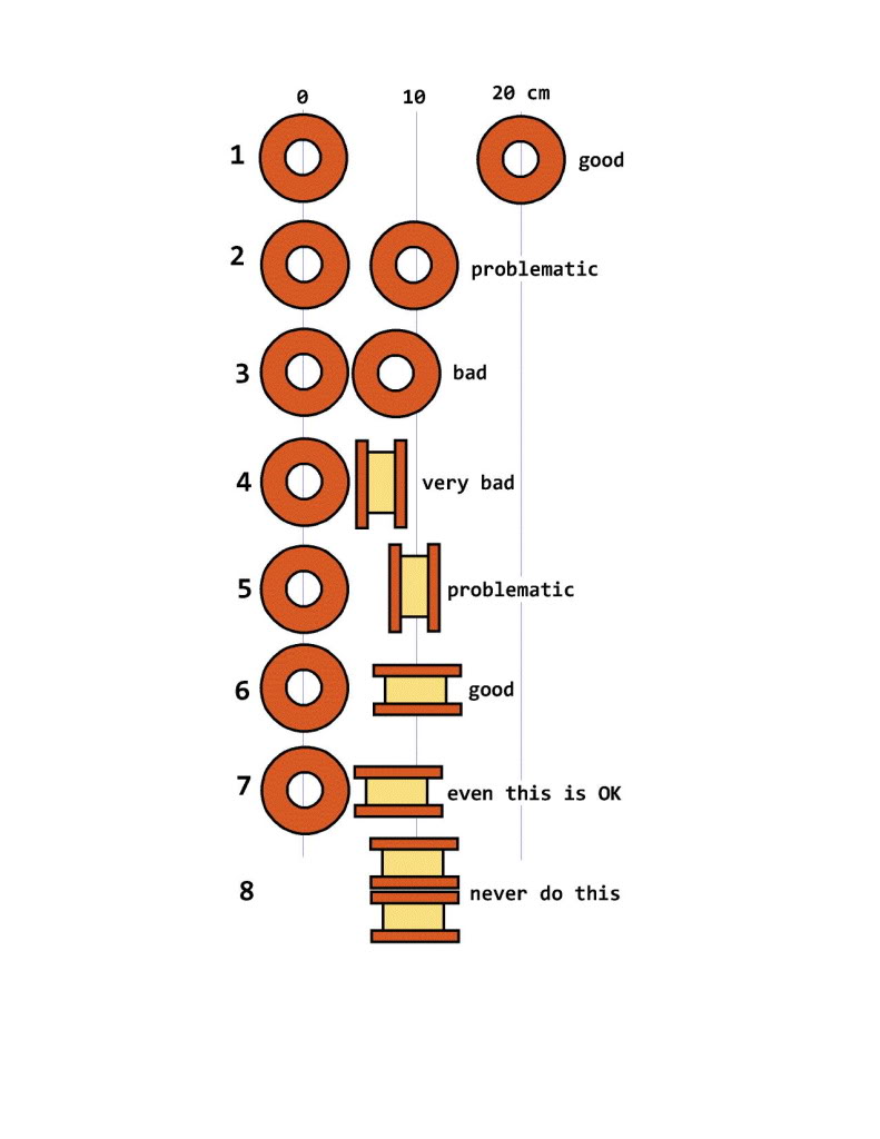
The issue with inductor placement is that if two inductors are close together there may be inductive coupling between the inductors. You can think of inductive coupling as a type of crosstalk between the circuits for each driver in a speaker. It is best to avoid inductive coupling. The best way to avoid inductive coupling is to ensure sufficient space between the inductors. The inverse square law applies. Doubling the distance reduces magnetic field strength by a factor of 4. There is plenty of room in most speaker cabinets to space out the inductors and ensure proper orientation to minimize coupling.

Positioning a third inductor between two inductors does not provide any shielding. It is a bad idea. Don't do it. You could use a magnetic shield, but there is a risk that the inductance could be affected by such a shield. No competent electrical engineer want to do such a thing in a crossover.

8166479100_1438618725.jpg

http://www.troelsgravesen.dk/coils.htm

Also, if one discovers too much filtering by an inductor, could a resistor be connected prior to and after the inductor (semi-bypass) to change it's crossover point?

What is too much filtering? That is very ambiguous. There are many characteristics related to crossover filters.

Inductors are used in low pass filters and in higher order, high pass filters. The inductors are critical for determining the crossover frequency and the slope of the curve. Adding a resistor to a crossover circuit has the potential to attenuate the signal to the driver and also affect the crossover frequency by changing the circuit impedance. Generally, resistors are not used in woofer circuits because of the power level applied to woofers.

Properly building a crossover requires good design followed by testing to tweak the circuit based on the drivers' response in the cabinet.

Check out this website for basic crosssover info: http://www.bcae1.com/xoorder.htm
 
Thank you for your reply. Much appreciated. I'm learnin'. I realize this isn't the most elegant of designs and I can find the typical and accepted way to build one but I'm a bit of a stubborn mad scientist, (with vain exageration on the scientist part).
I'm not trying to Rube Goldberg a crossover. I'm trying to keep it as simple as possible but options pop up like - "Oh lookie, I have some extra inductors laying around - it's a .9mH air core. What if I add that to the circuit in series with this Dayton 1mH 18ga solid core with .19 DCR? What? Nobody's done it, or at least, talked about it. Hmm. AudioKarma! "

I guess I'm looking for theoretical effects as well as practical ones. Right or wrong, I can't seem to find any lab results on the questions.
Even the Troels/G inductor layout only shows open core inductors in it's diagram. No mixing of the styles.

"What is too much filtering?" Perhaps my nomenclature is ill chosen. What I'd hoped to ask is if I find that I don't like what sounds I get, what effect would bypassing (but with a higher R value) give to the frequency passage and to the resistance level. The Dayton solid core is rated for 250 watts and can't imagine any saturation taking place from my moderately powered amp of 80w output.

Btw, the crossover is going into JBL L100 speakers which originally came without any inductor at all for the woofer so any inductor is going to help. Amp is a Nikko Alpha III mosfet.

I had some other questions about seemingly unheard of and probably ridiculable questions as well but my post was already getting diffused.
I'll keep the zener diodes, shielding material, and nanotoroids out of this for awhile.

All will be tempered with your offering... "No competent electrical engineer would want to do such a thing in a crossover."
 
Last edited:
What I have not seen or discussed anywhere on the web is the mixing of these styles in series for crossovers. Eg, solid core with an air core trailing it. Is there any benefit or detriment to this scheme?

Yes, that could be done, but under very specific circumstances with may not, in practice, ever occur.

Observation: series inductance adds, much as how parallel capacitance adds. So it is possible to fabricate larger values from smaller ones.

Consider, argumentum, a contrived situation where:
(a) a combination of acquisition cost, size, mass, and DCR constraints preclude a fully air-core solution​
— but —
(b) sonic requirements for distortion arising hysteresis and/or saturation preclude a fully iron-core solution.​

A hybrid would therefore be required to satisfy the constraints of this contrived example better than either type alone could.

It would therefore be possible to move to the middle of cost/weight and distortion (DCR, hysteresis, and saturation), by obtaining some of the inductance from an air-core inductor (higher cost, larger size, greater mass, higher DCR) and some from a iron-core inductor (lower cost, smaller size, lower mass, lower DCR).

This would, of course, be predicated upon the bedrock axioms that the trivial DCR of the air-core inductor actually mattered for sonic quality and that the distortion from the iron-core correspondingly did not have a significant effect upon sonic quality. Such assumptions would be mistaken.

This is a gedanken experiment and no one would in practice perform it. Hobbyists can scrape together the few dollars to move to air-core, and companies are generally so focused on price that iron-core would be a requirement to reduce overall cost, with the only choice being how much distortion to add, as the core type is a cost knob.

Also, if a third toroidal inductor is physically placed, perhaps vertically, between the other two inductors, does that put up a wall to protect all from electromagnetic fields?

Magnetic materials couple, never shield each other.

Special shielding materials are required to block magnetic fields. Look up µMetal or mu-Metal which was widely used in high-bandwidth CRT monitors and televisions to shield the gun from stray magnetic fields. Mu-metal is difficult to work with, as it must be annealed after welding or soldering.

RTally is totally correct about separating inductors, as the field strength varies as 1/r^2.

Also, if one discovers too much filtering by an inductor, could a resistor be connected prior to and after the inductor (semi-bypass) to change it's crossover point?

RTally is, again, totally correct about the purpose of a filter: it removes signal and separates the frequency band such that each driver receives the appropriate signal.

Your posited situation of wanting to attenuate a low-pass filter is generally improbable because the inductor is a low-pass filter, so it is intended to remove certain frequencies at 6 dB per octave. Such as with a woofer or as the ceiling for a band-pass filter used with, say, a midrange. So attenuating the filter would permit unwanted signal in the stop-band to enter the driver. This would not be desirable.

Permit me, however, to rephrase the question to one which is not nonsensical to pose.

Suppose, argumentum, that impedance compensation is desired to slightly flatten the driver's response in a very specific frequency range. A network of components, using either L or LC, is therefore required to shape the driver's response so as to make it better conform to the flat ideal.

Such a compensation network is, of course, placed in parallel with the driver and itself functions as a filter, albeit one which is limited in intensity for if it were not it would remove the entirety of signal in the pass-band. So the compensation network must be constructed as either a low-pass, high-pass, or band-pass, except that unlike the corresponding crossover filter for that frequency band the compensation network adds a resistor or voltage divider to substantially limit the current bypassed through the compensation network (in this case, argumentum, LC or L), because to fail to include the resistor or divider would act like a band-stop with the usual rolloff properties. So certain frequencies would be attenutated, but not removed in the traditional means. The resistor or divider would therefore limit the current through the inductor.

Attenuated filters are not generally used outside of compensation networks, as the only value would be to flatten response in a narrow region.

 
Thank you for your reply. Much appreciated. I'm learnin'. I realize this isn't the most elegant of designs and I can find the typical and accepted way to build one but I'm a bit of a stubborn mad scientist, (with vain exageration on the scientist part).
I'm not trying to Rube Goldberg a crossover. I'm trying to keep it as simple as possible but options pop up like - "Oh lookie, I have some extra inductors laying around - it's a .9mH air core. What if I add that to the circuit in series with this Dayton 1mH 18ga solid core with .19 DCR? What? Nobody's done it, or at least, talked about it. Hmm. AudioKarma! "

Sorry, but it really sounds like you are trying to emulate old Rube. The important part of being a scientist is the science part. Crossover design is not easy. It is the most difficult part of building a speaker. It helps to have a good grounding of electrical knowledge, plus the ability to test to tweak the design.

I guess I'm looking for theoretical effects as well as practical ones. Right or wrong, I can't seem to find any lab results on the questions.
Even the Troels/G inductor layout only shows open core inductors in it's diagram. No mixing of the styles.

I suggest studying up on inductors and how they work. With proper design and component selection, it is possible to build a good crossover regardless of type and number of inductors. I would not expect to see test results for various configurations because, for the most part, the questions you are wondering about are basic and easily addressed by having a good foundation of electrical principles. They don't need to be tested. But, unfortunately, there seems to be many who place undue significance on things that make no audible difference.

The inductor layout has to do with positioning inductors to avoid inductive coupling of the magnetic field generated by the inductors. Air cored inductors generate a large magnetic field. Cored inductors come in many flavors. Those with a rod-type core also generate a large, external magnetic field very similar to that of an air-cored inductor. The graphic above applies to inductors with rod-type cores. Toroidal and EI (laminated, transformer style) cores serve to contain most of the generated magnetic field so inductive coupling is rarely an issue.

"What is too much filtering?" Perhaps my nomenclature is ill chosen. What I'd hoped to ask is if I find that I don't like what sounds I get, what effect would bypassing (but with a higher R value) give to the frequency passage and to the resistance level. The Dayton solid core is rated for 250 watts and can't imagine any saturation taking place from my moderately powered amp of 80w output.

If you do not like the sounds you are hearing, you should then test with a real time analyzer (RTA) to determine WHY it sounds bad. Is there a hole or a peak somewhere? Is it at the crossover frequency or elsewhere? Without data, you have no idea what needs to be fixed. Just adding parts willy-nilly is putting the emphasis on "mad" as you emulate ol' Rube G.

Btw, the crossover is going into JBL L100 speakers which originally came without any inductor at all for the woofer so any inductor is going to help. Amp is a Nikko Alpha III mosfet.

I had some other questions about seemingly unheard of and probably ridiculable questions as well but my post was already getting diffused.
I'll keep the zener diodes, shielding material, and nanotoroids out of this for awhile.

All will be tempered with your offering... "No competent electrical engineer would want to do such a thing in a crossover."

My comment was to emphasize that electrical engineering principles are important, no matter how hard they are to understand. I started building electrical equipment as a young teen, but even after 4 years of engineering school and many working years, there is much I still have to learn. So, feel free to ask questions, but be prepared to spend a lot of time reading and learning because forum posts are not enough to learn what is needed.
 
A hybrid would therefore be required to satisfy the constraints of this contrived example better than either type alone could.

I'm going to run with the combo inductors for the woofer. Though I couldn't find anything specifically about mixing the different styles, the logic seems solid. I do have to space them out and semi-rotate them a tad more than they were though. Easy fix. Thank you gentlemen.

As far as the resistor question, well it was more of a theoretical question than an actual choice but your inputs are filed and appreciated.

I couldn't find any outside info on the toroidal inductor flux isolation question but will use yer'all's info to avoid crowding.

If forums aren't the place to learn about inductors, well, I have to start somewhere and, like Blanche Dubois, "I've always depended on the kindness of strangers."
Thanks again.
 
I wager you shall find the air-core preferable to the hybrid, and, furthermore, that you cannot hear the higher DCR (by about 0.5 Ω) of the air-core compared to the hybrid. The distortion of the iron-core will be slightly heard in an A/B during transients and afterwards, but it would not be noticeable or objectionable because of a lack of reference point. Speakers distort and humans tend to not notice this, unless it is particularly bad. (c.f. Bose or speakers overlapping drivers.)

Here's what I would suggest.
(1) Purchase inductors for both the single (air-core) and hybrid (air core and iron core).

(2) Wire one crossover using air-core for one speaker. Wire the other crossover using the inductor hybrid. Do not solder the inductors into the circuit, just use alligator clips. (Don't do fool-ass things like moving them around with the amplifier powered.)

(3) Play a mono signal and A/B to see which you like.

(4) Return the part(s) you don't like, double up on what you do like. Parts Express has a nice return policy.

(5) Report back that I was correct about the air-core sounding better.

(6) Listen to music. Rejoice in the sound achieved by small additional expenditure and DCR.​
 
I realized I did not post the rule of thumb for spacing.

I elsewhere posted this:

The inductors must be placed far enough apart that the fields do not interact. The rule of thumb suggests minimizing coupling between two air-core inductors in the same plane by ensuring that the inter-inductor distance is no less than 2.5 times the diameter of the larger inductor.

Which admittedly seems a bit much, but Troels (below cited) sets forth about four inches as sufficient for his example, and that seems to be in keeping with the rule given the diameters of those coils. I refer you to the work of Troels Gravesen, the master on the subject of inductor placement:

The most important aspect of crossover construction are:
(a) proper mounting of the inductors (above set forth); and
(b) proper securing of all components using non-conductive ties or mounts to prevent fracturing the solder joints via vibration from the sound.​

One suggestion: the crossover is best placed outside the cabinet for initial testing. Mistakes happen and inserting/removing the screws rapidly becomes time consuming and tedious. Plus the screw holes sometimes loosen and must be filled with epoxy, then drilled, etc.
 
One speaker is complete and I'm highly satisfied with the result. Much more relaxed and focused. In comparison, the original stock speaker sounds like a box throwing silverware at my ears. I didn't notice how garish the original speakers sounded until this left vs right expose'. I went "inside the box" with all new electronics with old tweeter and mid pots eliminated from circuit. Installed new terminals that will now accept 12 gauge wires. (The old spring clamps were a pain to accept large wire. Always fought them.)
I am now a JBL L100 backer. The old girls just needed some neural smoothing.
 
Last edited:
One speaker is complete and I'm highly satisfied with the result. Much more relaxed and focused. In comparison, the original stock speaker sounds like a box throwing silverware at my ears. [...] I went "inside the box" with all new electronics with old tweeter and mid pots eliminated from circuit.

Great that you like the new sound!

So you upgraded both (a) capacitors to film and (b) inductors to by a hybrid of air-core and iron-core?

What exactly changed?

I didn't notice how garish the original speakers sounded until this left vs right expose'.

Amazing, isn't it? Human hearing is quite poor in the abstract because the brain often does not know what it is hearing until it has a point of comparison. This is why I always suggest modifying one speaker and then doing an A/B comparison.
 
Great that you like the new sound!

So you upgraded both (a) capacitors to film and (b) inductors to by a hybrid of air-core and iron-core?

What exactly changed?

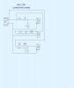
When I find the time I'll post the as-built schematic.

At higher volumes the original is too shimmery and piercing, The midrange is uncontrolled and harsh. Still listening in new and old mode. Kind of fun and interesting to adjust low, mid and high passes - to extremes - with an equalizer

Voicing on upgraded side is clear and full. Drums sound like drums. Crisp and tight with solid and deep bass. Volume hasn't gone past 1/2 with no problems. That's about all my ears can take. All drivers are original stock.

Short back story on speakers... They sat at my friends house for 30 years unused. His wife got them from her dad and they were just sitting at the end of a couch in his "man cave" being used as an end table for beer guzzling slobs like myself. They were always under a thin table cloth so I never knew they were there. I told her I'd clean them up for her and she said "Just take 'em". I followed her orders, obediently. I did replace them with a little chest of drawers for a table replacement. Still gotta set our beer down.
I put new grills on them as they had none - just that wood frame. I found some off white thin, open weave fabric (curtains?) at a thrift store and put those into another frame that's screwed to the existing removable frames. They look similar to Advents. I'll photo upload them some time soon.
 
When I find the time I'll post the as-built schematic.

I was just curious about the capacitor upgrade and inductor change, whether it was a mix of air-core and iron-core or purely air-core.

I know enough about filters and crossovers that likely no surprises are present. :)

At higher volumes the original is too shimmery and piercing, The midrange is uncontrolled and harsh. ... Voicing on upgraded side is clear and full. Drums sound like drums. Crisp and tight with solid and deep bass.

Could be the original woofer inductor was too high a gauge and began saturating at moderate volume. Maybe also leaky or high ESR capacitors on the midrange and tweeter, so overlapping is creating comb artifacts and distortion, plus consuming power as heat. I would not use the untweaked speaker as a bad capacitor could blow the tweeter.

Volume hasn't gone past 1/2 with no problems. That's about all my ears can take.

Yeah, well, this is why I can still hear to 16,000 Hz while my age cohort is running out at 8,000 Hz with bathtub curves in the response.

They look similar to Advents. I'll photo upload them some time soon.

Acoustic suspension drivers of that era may need to have the surrounds sealed to tighten up the bass. Also, the seal of the driver to the baffle may have hardened and may be leaking. Mortite was commonly used in those days and it eventually dries out and hardens.

Do not ever use anything other than butylene rubber solution sold by Vintage AR as it will ruin the drivers. Much discussion elsewhere on AK about the myriad of ways to fail.
 
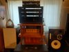
Yikes. No Ansel Adams am I.

(I realize speakers are too close together. Too much stuff in a narrow upstairs room.)
Name the man on the album cover on the upper left and win, well, bragging rights!
The integrated amp inside the modified wood end table is the left channel mono tuber. About 12 watts. There's another (not shown) underneath it inside the cab.
They are, at this time, connected to some Design Acoustics PS10 speakers.
JBL 100 pair connected to the black components above ... Nikko Alpha III amp, Beta 30 preamp and a Gamma 20 tuner.
EQ is an Audio Source.
CD player is Toshiba
 
Ok, basically a standard second-order crossover.

Adding series resistance to balance driver SPL is generally deprecated in favor of L-Pads. Manufacturers don't use that because of the cost and customers will maladjust and then complain. Same reason many digital cameras do not have a manual mode.

A fair bit of work has been done on the L100 to add RL impedance compensation to linearize the drivers. Not an expensive upgrade, either. You might consider doing that. All the heavy lifting has been done, only component ordering and soldering is required.

Most HiFi hobbyists have the identical problem of too much audio and not enough space.

Moving the speakers slightly away from the wall/window, and slightly angling them away from walls towards the sweet spot in which you sit, might yield better results. Are the cabinets slightly elevated off the floor? Coupling into the floor can reduce the bass. I have experienced the difference by moving the cabinets away from walls and floors. Depends on the speaker, but optimal for small rooms is typically approximately 8 to 24 inches from the wall and 3 inches raised off the floor. Yeah, I know, small space precludes golden mean placement, but we do what is possible because what else may one do in the face of hard limits like walls?
 
They are on stands about 15 inches tall.

Methinks I should start selling stuff. Pretty happy with my main setup and I have a stereo in every room. Even the bathroom.
index.php
 
Last edited:
Back
Top Bottom