Danzilla
Active Member
Okay. So picked up a pair of RSe speakers and refoamed them. Went to try them out and they sound decent... except for one of the EMIT tweeters isn't working.  I inspected it and checked it's resistance and seemed fine. So switched EMITs between speakers and sure enough, problem stayed with the speaker. So I figure there's a problem with the crossover. I open it up and pull out the fill and find that the two coils are both hanging free. Whatever glue they were on having lost it's hold. SOoooo... I figure yeah, it's the crossover. Check all the parts I can and find no issues. I finally go back to the fuse (that I had previously visually inspected and it looks perfect) and surprise surprise, it's reading between 2.X M Ohm and 500 K Ohm. Why do I say between? Because my meter can't seem to decide. Anyone else see that before? Where the fuse is essentially blown... but still connected and can pass a tiny current? Weird. I even double checked the fuse with a magnifier and can see the filiment all the way from one end to the other with no breaks... but it still isn't working right!
So first thing... for whatever reason, there's no Amp rating on this fuse. Just BUSS AGC and 250V. Makes no sense to me as Amp rating is kinda their their main purpose! Still, the other speaker has a different brand fuse and it's labeled 250V 2A. So fine. I only have some old spare 250V 1A fuses laying around, but that's good enough to test, and sure enough, that's all it needed. They're working fine and sound good.
Now then, what do I do about the loose coils?? They definitely need some good support as they're a bit heavy .2 mH coils. I was getting ready to JB Weld another driver's magnet later this week and considered doing the coils at the same time, but don't know if that's a great idea to use with the plastic/glue already in place. I really only use JB Weld on metal usually.
Any suggestions?


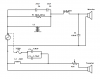
While I'm at it, does that crossover look right, to anyone that's worked with RSe speakers or similar Infinities? That little yellow piggyback cap in particular looks suspicious to me, like someone added it later. Not 100% sure, but looks like a tantalum cap and seems out of place with the rest. Update: I was just checking images I could find online* and there's definitely something odd with what I have. Not just the piggyback cap, but the big beige cap it's riding is different from OEM, plus the other big beige cap is complete absent in other examples I found, just like the piggyback! While I'm fine with replacing parts, like caps that have gone bad, redesigning is beyond me. I have no clue what was changed here or why. Any input would be appreciated.
Finally, though they are all working, when testing I did check ESR numbers on the caps in place and both the large beige caps (one is 6.8 K (uF?), 100V) read high. I know a good bit about basic electronics, but there's tons I don't know. Does a high equivalent series resistance necessarily mean they're bad, as I would expect if they were common polarized electrolytic caps that I'm more used to?
Thanks for sticking with me here. In the end it boils down to:
how should I best reattach the coils?
and
does that crossover look... right? If not, is there something else I should consider testing or consider replacing??
*Update question - the pictures I've found online (linked above) all have posts through the coils to help support them. Plastic or metal.. I'm not sure. Mine have none and don't look like they ever did. That likely just a design change from Infinity?
I inspected it and checked it's resistance and seemed fine. So switched EMITs between speakers and sure enough, problem stayed with the speaker. So I figure there's a problem with the crossover. I open it up and pull out the fill and find that the two coils are both hanging free. Whatever glue they were on having lost it's hold. SOoooo... I figure yeah, it's the crossover. Check all the parts I can and find no issues. I finally go back to the fuse (that I had previously visually inspected and it looks perfect) and surprise surprise, it's reading between 2.X M Ohm and 500 K Ohm. Why do I say between? Because my meter can't seem to decide. Anyone else see that before? Where the fuse is essentially blown... but still connected and can pass a tiny current? Weird. I even double checked the fuse with a magnifier and can see the filiment all the way from one end to the other with no breaks... but it still isn't working right!So first thing... for whatever reason, there's no Amp rating on this fuse. Just BUSS AGC and 250V. Makes no sense to me as Amp rating is kinda their their main purpose! Still, the other speaker has a different brand fuse and it's labeled 250V 2A. So fine. I only have some old spare 250V 1A fuses laying around, but that's good enough to test, and sure enough, that's all it needed. They're working fine and sound good.
Now then, what do I do about the loose coils?? They definitely need some good support as they're a bit heavy .2 mH coils. I was getting ready to JB Weld another driver's magnet later this week and considered doing the coils at the same time, but don't know if that's a great idea to use with the plastic/glue already in place. I really only use JB Weld on metal usually.
Any suggestions?
While I'm at it, does that crossover look right, to anyone that's worked with RSe speakers or similar Infinities? That little yellow piggyback cap in particular looks suspicious to me, like someone added it later. Not 100% sure, but looks like a tantalum cap and seems out of place with the rest. Update: I was just checking images I could find online* and there's definitely something odd with what I have. Not just the piggyback cap, but the big beige cap it's riding is different from OEM, plus the other big beige cap is complete absent in other examples I found, just like the piggyback! While I'm fine with replacing parts, like caps that have gone bad, redesigning is beyond me. I have no clue what was changed here or why. Any input would be appreciated.
Finally, though they are all working, when testing I did check ESR numbers on the caps in place and both the large beige caps (one is 6.8 K (uF?), 100V) read high. I know a good bit about basic electronics, but there's tons I don't know. Does a high equivalent series resistance necessarily mean they're bad, as I would expect if they were common polarized electrolytic caps that I'm more used to?
Thanks for sticking with me here. In the end it boils down to:
how should I best reattach the coils?
and
does that crossover look... right? If not, is there something else I should consider testing or consider replacing??
*Update question - the pictures I've found online (linked above) all have posts through the coils to help support them. Plastic or metal.. I'm not sure. Mine have none and don't look like they ever did. That likely just a design change from Infinity?
Last edited: