quicksand
Active Member
I am about to install cathode resistors in a Fisher amp that uses 7868 OPTs.
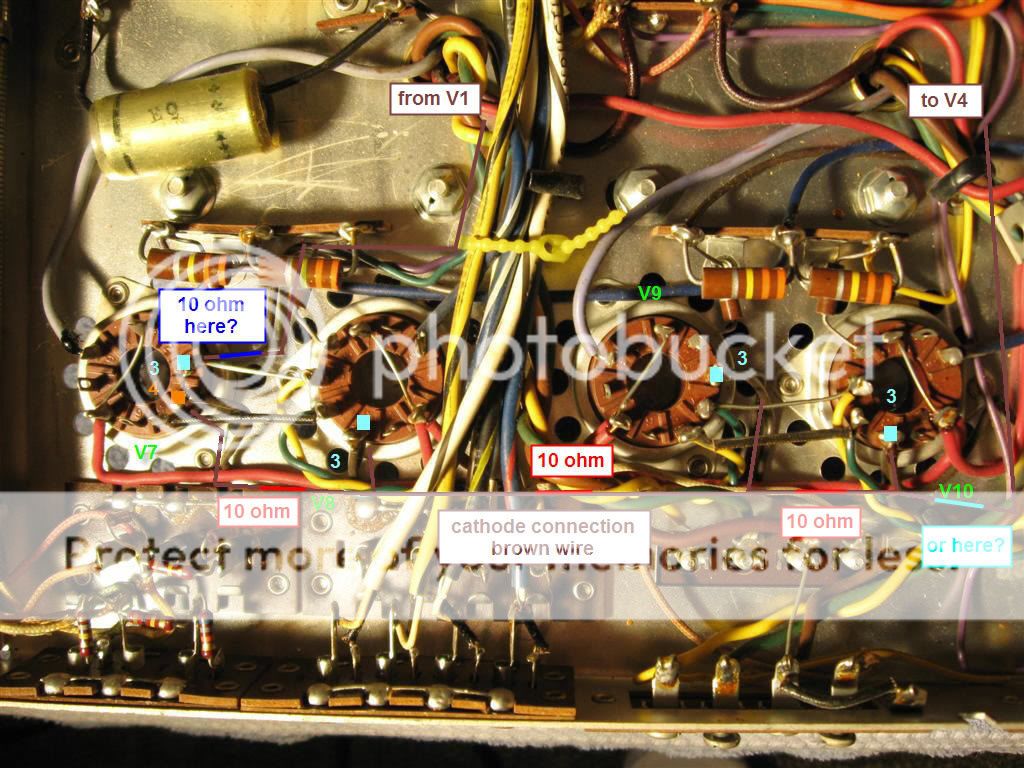
Below is the schematic and a picture of the bottom. I put 4 red rectangles where I think the cathode resistor should be installed - ignore the highlighter.

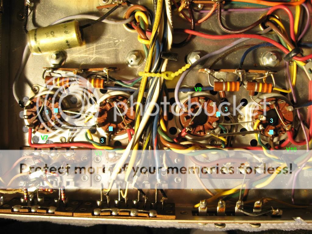
The Cathode is pin 3
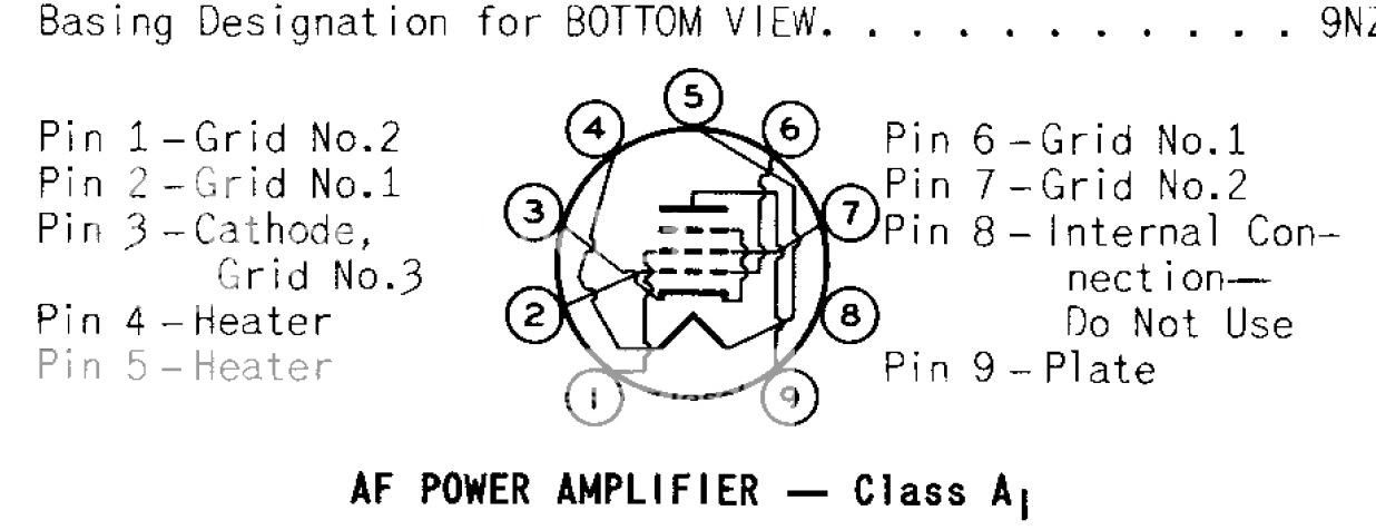
The 10 ohm resistors should go from pin 3 directly to ground from what I read.
There is a brown wire that runs from pin 3 to pin 4 on V7 - from there the brown wire continues to the other 3 pins on V8,9,10.
If I splice the brown wire before pin 3 on all tubes and install the resistor at the splice is this correct?
It seems that the only cathode resistor is needed but I am following what I have read.
Entire schematic: Click to enlarge - Ignore the highlighter.

---
A simple question about the bias pot adjustment. Currently V7 is red plating and I want to set the bias as low as possible at start.
Is adjusting/turning the pot all the way left the the lowest setting or right? I am guessing left but just want to make sure.
Thanks!
Below is the schematic and a picture of the bottom. I put 4 red rectangles where I think the cathode resistor should be installed - ignore the highlighter.
The Cathode is pin 3
The 10 ohm resistors should go from pin 3 directly to ground from what I read.
There is a brown wire that runs from pin 3 to pin 4 on V7 - from there the brown wire continues to the other 3 pins on V8,9,10.
If I splice the brown wire before pin 3 on all tubes and install the resistor at the splice is this correct?
It seems that the only cathode resistor is needed but I am following what I have read.
Entire schematic: Click to enlarge - Ignore the highlighter.

---
A simple question about the bias pot adjustment. Currently V7 is red plating and I want to set the bias as low as possible at start.
Is adjusting/turning the pot all the way left the the lowest setting or right? I am guessing left but just want to make sure.
Thanks!