• The move to the new server is done. There are some software and database maintenance updates in process. This has us passing the hat around to help out. We appreciate any donations. Seriously, even a dollar helps. The payment page may be found here - https://www.audiokarma.org/support.html

Interelectronics Model 85 Consolette Preamp Information Request

tcdriver

AK Subscriber
Subscriber
I have an Interelectronics One Hundred amplifier and I am interested in finding out information on the Model 85 Consolette preamp. The preamp was designed to draw its power from either the power amplifier or a stand alone power supply. What I would like to know is:

What are the B+ Voltage and Current requirements for the Consolette preamp?

I already know the filaments requirements are: 6.3Vac @ 0.8A.

Is there a schematic available for the preamp?

I would also be interested in hearing from anyone who has experience with using the preamp with or without the power amplifier. How well did the combination work out?

Thanks.
 
Register to hide this ad
if you have a schematic for the power amp, possible the B+ stuff could be worked out from there.
Yes, thanks for the thoughtful reply. I have tried to work it out just as you suggested. I do not have a complete and accurate schematic. The filament voltage and current are OK. what I would like to know is how much the preamp will load down the voltages to the power amplifier's front end? Will the 27k ohm resistor need to be adjusted down?

Here is what I know.

There is an octal socket on the side of the power amp chassis with the following connections:

pin 1 Ground
pin 2 filament
pin 3 B+ (268VDC)
pin 4 power amp power switch
pin 5 power amp power switch
pin 6 no connection
pin 7 filament
pin 8 no connection​

The power amplifier tube complement is:

1 ea. 6SL7
1 ea. 6SN7
2 ea. 7581
1 ea. 5U4GB​

The preamp tube complement is:

1 ea. Z-729/EF86 filament = 6.3v @ 0.2A
1 ea. 12AY7 filament = 6.3v@0.3A
1 ea. 12AX7 filament = 6.3v@0.3A​

Amplifier power supply:
Power Supply.jpg
 
having a poke at the datasheets, its probably about 1ma for the EF86, about 1.5ma total for the 12AX7, and maybe 6ma for the 12AY7, so ballpark of 8ma. 8ma across 27k drops 216 volts so either that resistor needs to be smaller, or I'm way off on the guesstimate of current load.

I don't suppose this has a dummy plug for the preamp that connects it to a resistor when the preamp isn't connected ? My Pilot 260 is set up that way so the voltages are constant even if the preamp is not connected.
 
I built a separate power supply for one of my Magnavox's tuner preamp as it originally used the main amp for its power.

I built my power supply to 250 volt, 1 amp minimum spec. Works fine on any other power amplifier of my choice.
 
having a poke at the datasheets, its probably about 1ma for the EF86, about 1.5ma total for the 12AX7, and maybe 6ma for the 12AY7, so ballpark of 8ma. 8ma across 27k drops 216 volts so either that resistor needs to be smaller, or I'm way off on the guesstimate of current load....
Yes, that is exactly what puzzled me. I wonder if the manual called for changing the 27kΩ resistor or the tubes were being operated at a low plate current. :dunno:

...I don't suppose this has a dummy plug for the preamp that connects it to a resistor when the preamp isn't connected? My Pilot 260 is set up that way so the voltages are constant even if the preamp is not connected.
My Pilot SA-232 did that also. I do not see that here. According to the review in High Fidelity magazine, there was a stand alone power supply available if one did not power the preamp from the amplifier, although, I have never seen pictures or specifications for what may be that mythical beast.
 
You might check the wiring in the amp again. The Heathkit W4 has a 22K resistor for the preamp B+ coming off a much earlier point in the decoupling string.
 
That would make a lot more sense honestly, tapping off the far end would affect voltages everywhere along the path. Having it fed off fairly early after a small resistor would make any change to the voltages within the amp minimal.
 
You might check the wiring in the amp again. The Heathkit W4 has a 22K resistor for the preamp B+ coming off a much earlier point in the decoupling string.
Thank you for your suggestion. I just measured the resistance from the 27kΩ resistor to pin three on the "PREAMP" socket and it was a short. that means I was correct that they did tap at the end of the CRCRCRC chain to the preamp. :dunno:

That would make a lot more sense honestly, tapping off the far end would affect voltages everywhere along the path. Having it fed off fairly early after a small resistor would make any change to the voltages within the amp minimal.
Yes, I would agree that it might make more sense to tap off an earlier branch but, that is not what they did.
 
I have a question for everyone -- what is the justification for using a dropping resistor as opposed to a voltage divider? Wouldn't the latter be less responsive to current variations? Is it just the extra parts and the extra power consumption, or is there a performance reason?
 
A voltage divider costs more than a dropping resistor, two resistors is twice the price, and it likely wastes more current because the shunt is always loading the supply and burning current, whereas the current draw from a dropping resistor depends upon the load actually using current.

In a preamplifier, typically running pure Class A at relatively little current, the load remains constant which is why a dropping resistor works: constant load equals constant voltage drop. The voltage divider provides a constant drop because it uses two resistors, so it is suitable for applications with a variable-load.

But, again, cost always was a factor for these consumer products and carbon-composition resistors actually cost an impressive amount of money, likely about five to ten times today's cost, for what we would today consider to be a component inferior to modern metal-film resistors.

The optimal way is to use a modern low-dropout voltage regulator to provide rock-stable power with essentially no noise.
 
^^ yup, this. With a steady load there just isn't any need to build a more robust and therefore more expensive power supply.

Now with active regulation the other benefit you get is extremely good ripple rejection. Still don't exactly require it but a quiet supply is rarely a bad thing. In theory a money is no object designer in 1955 could have done a fully active regulated supply with no ripple to speak of, but it would have involved as many tubes in the power supply as it was feeding, plus all the power transformer an chassis space required to make all that happen. All of that turns into a lot of dollars to get something that a couple of resistors and caps could do almost as well for a whole lot less money.
 
Yeah, makes sense. And I guess circa tens of volts difference based on slight variations in current draw doesn't really matter.
 
One way or the other, my guess is that you're look at about a 250vdc supply for the preamp. I think if you wanted to build a separate PS, I'd shoot for that range, with a way to adjust it, even if it's just swapping rectifiers to get more or less voltage. Then play around with it until you get some reasonable plate and cathode voltages on the tubes. I don't think you can hurt it and it will probably work just fine.
 
Also, the Heathkit WA-P1 used a 12AY7 and a 12AX7 interchangeably, so the 12AY7 is probably running at very low current. You might look at the Heathkit W2 manual for a guide to operating voltages for the Coronette. They're in the range of 75-90 plate volts, with 1.5 volts on the input tube cathode, which would be typical. The stated supply voltage for the WA-P1 is 220vdc.
 
Issues of voltage regulation arise from when a Class AB amplifier's power supply also powers the amplifier's Class A preamplifier. So running the preamplifier from the amplifier's power supply might not be the best situation if the amplifier's supply is insufficiently stiff.

Here's a handwavy explanation of how and why that happens. The truth is that I'm uncertain it matters in practice for "normal" volume levels, as once the amplifier falls off the distortion cliff it's all over, and finger pointing to which section contributed the worst of the distortion becomes pointless.

Class A
In Class A the load is very nearly constant — a first order approximation would say that it behaves as constant — so the passive (linear) voltage regulator — some variant of RC, LC, or LRC instead of active silicon — in the power supply may be far simpler, typically a few cascaded stages of LC filter to remove the majority of the ripple current and noise. A current reservoir — be it some combination of charge stored in capacitors or flux in inductors/chokes — is a needless expense since the load is not fluctuating. With steady state an adequate supply will always be adequate.

Because preamplifiers are Class A and low power, their voltage demands on the power supply are both constant and minimal, the greatest improvement arises in terms of reducing the ripple current and noise which may otherwise be amplified in the high-gain front-end and the subsequent cascade of gain stages.

Class AB
In a Class AB (or Class B for that matter) output stage which is reproducing fast-moving transients the current demands rapidly fluctuate.

A rapid response, in consequence, is required from the power supply to avoid voltage sag, or distortion results. So the power supply must be low impedance to be able to rapidly respond to fluctuating demand without degradation in the B+. (This requirement is true for tube amplifiers as well as solid state; it's all about reserve capacity for transients.) Either isolated RC stages or big chokes were added to serve as the current/charge reservoir, and the amplifier designer was limited in stiffening the supply by the considerable expense for the choke or filter capacitors.

In the old days voltage regulators required multiple tubes and were very, very expensive. I have a tube regulated power supply with no ripple which cost three times what the Dynaco ST-70 cost. Pricey. I will some day restore it as a curiosity to power my breadboard. Modern regulators are far, far superior as the regulator rapidly increases the voltage to prevent sag from current peaks, consequently appearing to the load as an ultra-low-impedance supply, unlike the multiple stages of RC filters which have a charging time and resistive losses.

Piggybacking Class A Preamplifier on Same Supply for Class B Output Stage
The problem arises when the preamplifier piggybacks on the B+ supply for the power amplifier, such that preamplifier and amplifier now use a single, identical source of B+.

In such circumstance any modulation of the B+ by the Class AB amplifier output stage will simultaneously modulate the supply for the preamplifier, even though it is Class A with a constant load. Think of this as the dog (Class AB output stage) wagging its tail (Class A preamplifier stage). Conversely, one could argue that the (tail) preamplifier increases demand for B+ and thereby correspondingly increases the risk of voltage sag during peaks for the (dog) amplifier. That would speak to an inadequately designed power supply; why provide a tap, if using it would (routinely or significantly) degrade the sound?

The fact is that integrated amplifiers typically used the same supply, with a dropping resistor — as per earlier discussions about the constant load of Class A nicely lending itself to a single resistor — for down-regulating the higher B+ used for the Class AB output section into a lower B+ for the preamplifier, and nobody worried about modulation of the preamplifier by the output stage. The designers might have added enough reserve capacity to generally prevent sag, so it would only be the greatest transients which would cause noticeable sag, and thus distortion in the output stage, which usually is minor for moderate listening levels.

Amplifier separates, such as Dynaco, Fisher, Interelectronics, etc. commonly used plugs and cables to power a physically separate preamplifier chassis from the Class AB output supply. Separate power supplies were available to use the preamplifier with other equipment lacking a power-supply tap for external devices. A separate preamplifier supply, of course, reduces the need to stiffen the amplifier supply to better deal with transients.

Conclusion
Having written all of that, in the external preamplifier or integrated tube amplifiers we commonly see, the fast-moving transients in the amplifier's output stage likely do not cause significant distortion in the preamplifier audible, at least above and beyond the distortion already arising in the output stage.

By that I am suggesting and speculating that at output levels sufficient to stress the supply the resulting distortion is so significant that it is difficult to say how much results from the modulation of the power supply affecting the preamplifier stage, versus how much is simply the output stage clipping, distorting, or otherwise failing, and the preamplifier stage coming along for the ride on that distortion rollercoaster.

So it is not entirely clear that any defect in the stiffness of the Internelectronics supply for transients would deleteriously affect the preamplifier stage, or, conversely, that the tiny draw from the preamplifier would rob the amplifier's output section of necessary current and thereby result in voltage sag.

Determining the effect would need some measurements, which would be interesting to see as it might reveal some fundamental truth. As the kids would say, UR PREAMPLIFIER POWER, UR DOIN' IT WRONG!!! Or, maybe we're all doing it correct. Absent hard data, who knows?

 
Here's a thread where someone drew out the 400 amp schematic. I could be wrong, but it looks like a 2.7K resistor to the preamp...
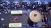
Thank you for your suggestion. I just rechecked the resistor. It measures 29.4kΩ. The color code on the resistor indicates 27kΩ, 10%. The resistor is within the 10% rating. You may be able to see the resistor on the right hand side of this picture sitting right next to the 15KΩ resistor:
Interelectronics (9).jpg

Yes, I am aware of that thread and that schematic. It shows 27kΩ.
 
Thank you for your suggestion. I just rechecked the resistor. It measures 29.4kΩ. The color code on the resistor indicates 27kΩ, 10%. The resistor is within the 10% rating. You may be able to see the resistor on the right hand side of this picture sitting right next to the 15KΩ resistor:
View attachment 2579376

Yes, I am aware of that thread and that schematic. It shows 27kΩ.

You're right, it does. Well, with a few mA current draw, it looks like maybe a supply of 150vdc? I guess all you can do is experiment.
 
Back
Top Bottom