• The move to the new server is done. There are some software and database maintenance updates in process. This has us passing the hat around to help out. We appreciate any donations. Seriously, even a dollar helps. The payment page may be found here - https://www.audiokarma.org/support.html

Interesting Electro voice Sentry III speakers found

robiles

Active Member
I have been lucky enough to find 4 of the above mentioned speaker for sale locally, for what can be called a steal. After scheduling a pick-up time and date, i looked at the photos more carefully, and noticed that they actually look like replicas - but still decided to take a look at them.

After meeting the owner, he started to tell me the story of the speakers: they were bought as a kit from electro voice (drivers and crossover), and the cabinets where custom made by a carpenter (port upgrade included) after detailed plans from EV. According to him, the sat unused for the last 8 year, and have rotted foam surrounds. Took the woofer off and indeed, the crossover plate was visible behinf the insulating material, with "Electro-Voice" and "Sentry III" written on it.

Now comes the somewhat strange part: the crossover is totally different to the ones that i found on the web. My guess is that the pictures i saw where of the series II while this is from the series I.

Now i have a couple of questions, maybe there is somebody out there who can help me:
- how can i tell which of the series this belongs to other than optics, and how to determin what drivers are installed (there is nothing written on them except a serial number)?
- the terminals at the back are "single" - so that bi-amping ist not possible at the moment. I have ordered bi-amping terminals that i wanted to install, but i have no idea how to connect the wires properly - probably has something to do with the 1 - 4 connectors on the crossover?
- there are 2 MKP capacitors and 1 plain capacitor - do the MKP ones age and need to be replaced like the electrolytic ones? Plan on testing them with a cheap parts tester and see how they measure, and will only replace them if values have shifted beyond the 20% or so tolerance.

My guess is also that there are DACH (Germany, Austria and Switzerland) products, as the writing on the crossovers is in german. Also received a Interface B EQ (soon to be converted) that has a Switzerland sticker.

Thank you all in advance, and if further photos are needed, i can gladly upload some more
 

Attachments

  • IMG-20210613-WA0012.jpg
    IMG-20210613-WA0012.jpg
    114.3 KB · Views: 329
Register to hide this ad
The crossover doesn't impress me. 5 inductors all in the same plain and not far apart?

Do not recall seeing any crossover plans that called attention to a huge difference between Series 1 and II but not sure on that. Guess you won't know how good or bad the crossover is until fixing the woofer surrounds.

Would enjoy some pictures of the cabinets. Did you pick up all four cabinets?

EV3
 
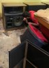
I only managed to pick up 2 of them, because my car was not big enough for all 4, but the other ones are safely stored for a later pick-up. The grills also had to be left behind because of bad planing.

Do you know how to check if the speakers are genuine or not?

Here is a photo of me next to them.
 

Attachments

  • IMG-20210613-WA0011.jpg
    IMG-20210613-WA0011.jpg
    92.4 KB · Views: 247
The crossover doesn't impress me. 5 inductors all in the same plain and not far apart?

Do not recall seeing any crossover plans that called attention to a huge difference between Series 1 and II but not sure on that. Guess you won't know how good or bad the crossover is until fixing the woofer surrounds.

Would enjoy some pictures of the cabinets. Did you pick up all four cabinets?

EV3

Do you have any clue about the posibility of converting these to a bi-amp setup?
Would also be interested in knowing where/how was the insulation material placed in the speakers. At the moment there is insulation only on the back wall and on the side wall next to the ports.
 
Do you know how to check if the speakers are genuine or not?

Unfortunately your suspicion is correct not genuine, at least as far as the cabinets, crossover and grills.
SM-120 and ST-350 look fine the woofer does have a foam surround but you would need to pull it and
get a pic of the rear for further confirmation.

Also I've yet to see a Sentry III with the reverse baffle layout on the one pictured.
 
Unfortunately your suspicion is correct not genuine, at least as far as the cabinets, crossover and grills.
SM-120 and ST-350 look fine the woofer does have a foam surround but you would need to pull it and
get a pic of the rear for further confirmation.

Also I've yet to see a Sentry III with the reverse baffle layout on the one pictured.

I knew from the owner that the cabinet are not genuine. I was reffering to the drivers themselves (or how are they called) - but i have since taken all the drivers out, and they all look genuine to me - hard to be 100% because there is only a serial nr. on them (Except the 1824 that has a EV sticker on). Crossovers might be simplified (special edition for Europe maybe) due to this being bought as a kit, with all components from EV, and diy cabs.

By reverse baflle you mean the layout of the speaker is mirrored? The cabinets are made as pairs, and are simetrical.
 
Unless my memory is foggy today, my Series II have the 1823 on the mids. And I thought early versions used the 1824. Don't take that as gospel.

I saved the crossover picture and brought it up as a photo so I could pull it up closer and after seeing the logo of EV on it, I'd speculate that crossover came with the drivers from EV maybe. If so then the construction and values used should be all appropriate. Don't know if they changed anything regarding crossover points between the two versions. Not that I've seen, though that doesn't mean much.

Separating into ability to drive them bi-amped. First I would question what those other pins that are not wired are. I can't see the legends on them well enough to tell anything. But if you are able to draw the circuit, it shouldn't be too hard to figure out.

Do get that eq going. It's well worth use. What it adds at the bottom end feels like more than the numbers would suggest.

Here is a version of the drawing of the crossover I have. The switching on the left side, upper input might not be on your unit based on the small number of mounted parts. And the accenting highs is on the external EQ anyway. And then the section with the diodes, centered around the cap, thats the protective device and isn't in yours as shown anyway. So what you're left with might come close. Looks like cap and inductor on the HF. The mids using the 2 inductors, 2 caps and 2 resistors. Then the bottom for the low pass using a single inductor and a cap or two. See how close that looks.

ST8ztjl.jpg


The crossover built in on mine and another set I've got and all I've seen pictured, look like this.
Qpee8MA.jpg


If you can read it, hear is my hand written notes on values as measured and/or noted on the parts.

ZFIE320.jpg


EV3
 
Unless my memory is foggy today, my Series II have the 1823 on the mids. And I thought early versions used the 1824. Don't take that as gospel.

I saved the crossover picture and brought it up as a photo so I could pull it up closer and after seeing the logo of EV on it, I'd speculate that crossover came with the drivers from EV maybe. If so then the construction and values used should be all appropriate. Don't know if they changed anything regarding crossover points between the two versions. Not that I've seen, though that doesn't mean much.

Separating into ability to drive them bi-amped. First I would question what those other pins that are not wired are. I can't see the legends on them well enough to tell anything. But if you are able to draw the circuit, it shouldn't be too hard to figure out.

Do get that eq going. It's well worth use. What it adds at the bottom end feels like more than the numbers would suggest.

Here is a version of the drawing of the crossover I have. The switching on the left side, upper input might not be on your unit based on the small number of mounted parts. And the accenting highs is on the external EQ anyway. And then the section with the diodes, centered around the cap, thats the protective device and isn't in yours as shown anyway. So what you're left with might come close. Looks like cap and inductor on the HF. The mids using the 2 inductors, 2 caps and 2 resistors. Then the bottom for the low pass using a single inductor and a cap or two. See how close that looks.

ST8ztjl.jpg


The crossover built in on mine and another set I've got and all I've seen pictured, look like this.
Qpee8MA.jpg


If you can read it, hear is my hand written notes on values as measured and/or noted on the parts.

ZFIE320.jpg


EV3

Wow, that is one nicely (and detailed) written answer, Thank you for taking the time to do it.

I am a beginner in this field, so drawing circuits is really not my thing. I will try to remove the crossover and take a photo of the back - should be easy to figure out. Thee pins that are unused are marked with 1, 2, 3 and 4, and thee ones used are marked with input, + and -. What you have written regarding the two types of crossovers is most probably true - here is a list of thee components that are marked with the specs:

C1 62 uf
C3 33 uf
C4 15 uf
C5 1,5 uf

R1 10 Ω
R2 3,3 Ω
R3 8,2 Ω
R4 3,3 Ω
R5 2,2 Ω

Capacitors are pretty clear, and i assume the big 62 uf cap is used instead of the two 30uf's for the LF, while the others are not that far from off your specs. As to what effect the changes in values for both caps and resistors is for me not that important. Importan for me was to confirm that these are actual EV components, and not some cheap but good looking fakes.

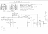
Also sent an e-mail to EV Germany and they could only send me the circuit diagram, as it is the only thing they have left:

upload_2021-6-15_8-5-34.png

Will post again soon after i manage to take the crossover dow, for further investigation.

One more request, regarding the insulation material - on these there are only 2 surfaces that are insulated, but from my research, there should be more, but did not se clear pictures, only what was visible thru holes. Could you please describe how they are normaly placed?
 
OEM Cabinets were not mirrored.

I already knew that. It is a known fact that they had to cut some corners (did anybody say reflex port?) to be able to sell them as cheap as they did. I have a certain dislike for speakers like this, and consider it a deesign flaw, but still have and use such product - grilles make it all a bit better, but not always perfect.
 
Thanks for sharing the drawing from EV Germany. The bi-amping wire jumpering is the same as what I've saved previously. Obviously, you don't have that setup like that.

The values shown for the difference between the 1824 and 1823 on the mids I don't think I'd noted before. Good to know.

With regards to the question about cabinet stuffing. I don't think I have any pictures to refresh my memory inside mine. But I don't recall there being a whole lot inside. Stuffing is mostly to change the volume of a cabinet and what you have pictured for cabinet size looks like same as the original. I'd suspect you could throw in a cut piece or two of Owens Corning 703 and not change things much one or the other. But certainly don't overdue until you have a chance to hear it the way it is. Know that you only have the woofer firing into the box and none of the various materials used inside speakers is very effective at sound deadening very low in frequency. Its use is more to change air flow, effecting interior volume more than any 'deadening' properties.

If your crossover follows pretty much the above drawing (maybe minus the STR tweeter protector and/or the HF peaking switch) then the two paths to focus on for bi-amping is the inside 'loop' for the woofer and the outside 'loop' for the mids and HF. In that drawing to separate, it's a matter of opening the two jumpers, those on the top and on the bottom, labeled 'bi amp in'.

If you can supply a photo of the back of the crossover and its able to be referenced to the face picture, then we should be able to determine how to go about separating the lows for bi-amping.

EV3
 
Thanks for sharing the drawing from EV Germany. The bi-amping wire jumpering is the same as what I've saved previously. Obviously, you don't have that setup like that.

The values shown for the difference between the 1824 and 1823 on the mids I don't think I'd noted before. Good to know.

With regards to the question about cabinet stuffing. I don't think I have any pictures to refresh my memory inside mine. But I don't recall there being a whole lot inside. Stuffing is mostly to change the volume of a cabinet and what you have pictured for cabinet size looks like same as the original. I'd suspect you could throw in a cut piece or two of Owens Corning 703 and not change things much one or the other. But certainly don't overdue until you have a chance to hear it the way it is. Know that you only have the woofer firing into the box and none of the various materials used inside speakers is very effective at sound deadening very low in frequency. Its use is more to change air flow, effecting interior volume more than any 'deadening' properties.

If your crossover follows pretty much the above drawing (maybe minus the STR tweeter protector and/or the HF peaking switch) then the two paths to focus on for bi-amping is the inside 'loop' for the woofer and the outside 'loop' for the mids and HF. In that drawing to separate, it's a matter of opening the two jumpers, those on the top and on the bottom, labeled 'bi amp in'.

If you can supply a photo of the back of the crossover and its able to be referenced to the face picture, then we should be able to determine how to go about separating the lows for bi-amping.

EV3

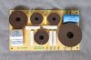
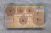
So, here a couple of fotos of the crossover, one clean, and the other with the bottom merged on top:

Crossover Front.jpg


Crossover Front-Back.jpg

Further than that i am clueless as to what could lead where, as i am a noob in this regard. I try to pick up new things as i go, but t his is a bit too complex for me.
Really apreciate your help, and if you-re ever in Frankfurt, look me up and i will buy you a couple of cold ones.

Now i have to wait untill the surrounds are delivered and after that they will have to be put to the test with my meager 30WPC Integrated amp.
 

Attachments

  • Crossover Front.jpg
    Crossover Front.jpg
    136.9 KB · Views: 21
Nice job on flipping the trace side and putting it under the components. But I am having trouble seeing the traces towards the left side above. Can you post a clear shot of the bottom (either way rotation is fine) so I can better see the trace breaks. Does look like the way it's layed out is headed to being the same as the drawing you were provided.

A couple questions. Can you see if the yellow square part between the two inductors and next to the middle of the three outputs...is that an adjustable resistor? I thought it'd have a third leg under it but don't see that. Trying to see if it's the 8 ohm, adjusted to 3.5 ohms that goes to the mid, minus side. And can you read the output labels and convert them for me to Bass, Mid and Highs. I think as pictured it will eventually confirm to be left to right, Mid, Highs and Bass. Is that right?

Looks like the 1, 2, 3, 4 are to wire out to the HF level switch as shown above which you don't have. Again, not really significant when using the external EQ that also has HF adjustment.

If I happen to look up someday and realize I'm in Frankfurt, cold ones accepted!! :beerchug:

EV3
 
Here is a shot of the Crossover's underside:

21_P1465.JPG

The in pins are on the top right side, and the out pins are on the bottom, from left to righ: mids (mitte), highs (hoch), and bass. The order of the out pins you presumed is correct.

The yellow rectangle is actually a 1.5uF/10/100 (MKT) Capacitor.

If i understood correctly, than there is no possibility for a bi-amp wiring. For me it is not such a big deal as i do not have 2 amps at the moment, but would have like tto make them as close to original as possible.

I also got a B equaliser, that i already found out how to convert to a SEQ equaliser. I have understood that it is to be placed between pre- and poweramp, and close the bottom reflex port.

edit: as i want to learnn aboutt circuits and such, i compared the crossover with the schematics, and thought about what could bedone for bi-amping to be possible. I have sketched where i think a beak in the circuit can separate the LF (marked with A) from MF and HF (market with B). The actual + and - in would be for LF. Could the MF and HF be driven bby simply solder some wirees to the board, somewhere on the marked surface?

upload_2021-6-16_10-6-23.png

I might also be wrong, so please feel free to correct me if i'm wrong.

edit 2: is there a reason to change the 62 uF electrolytic capacitor? From what i have gathered, the MKP ones are not as affected by age. I have a cheap parts tester that i could use, but would unsolder only if needed (my knowledge is that caps parallel to drivers are not that critical to sound as those in series, but might also be wrong)
 
Last edited:
Maybe somebody else out there that can help me? I only need to find out if my theory to tune the Crossover, to allow dual amping use, is true.
 
Can't help with the crossover schematic, but it is odd that the inductors are layed out like that.
 
All i know is that the crossover design is slightly simplifed compared to the "real" ones. But i find the enclosures itself is better built than the originals: port hole is already improved and the layout is symetrical (ev had to keep the cost at bay). On the downside, they do not look as good.
 

That is one informative thread, but sadly it does not help me with my (bi-amp) problem. Mine come with a clasic crossover - all the pieces soldered to a board.

Are those Heresy's i see in your photos? As my place is much too small for the Sentry's, i thought about replacing them with Heresy's, and am curious to know how they sound in comparison...
 
That is one informative thread, but sadly it does not help me with my (bi-amp) problem. Mine come with a clasic crossover - all the pieces soldered to a board.

Are those Heresy's i see in your photos? As my place is much too small for the Sentry's, i thought about replacing them with Heresy's, and am curious to know how they sound in comparison...
The Heresy's have moved on, someone purchased them to have in their record shop they were opening. They don't compare well to the Sentry III's, the EV's have one of the best midrange horns ever in my opinion, and others have said this also. I wouldn't worry too much about biamping if I were you, you can always build specific crossovers at some point to do that down the road. I ran my III's on 60 watt tube gear for quite some time, and only recently hooked them to my high power solid state gear. They certainly like wattage and seem more balanced with not as much a need to biamp.
 
Back
Top Bottom