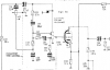
• The move to the new server is done. There are some software and database maintenance updates in process. This has us passing the hat around to help out. We appreciate any donations. Seriously, even a dollar helps. The payment page may be found here - https://www.audiokarma.org/support.html

Is this a Selenium rectifier?

linuxslate

Well-Known Member
Background:
I have a Grundig RF-250U on the bench. I wanted a tube table radio for a while, and I wanted stereo, and a magic eye tuning tube. So when I came a cross a Grundig RF-250U locally, I went for it.

Overall the unit is complete, mostly original, and very good cosmetically, but it needs some help in several areas.

Right now, I am dealing with a failed bridge rectifier. (B250C100). It was bulged, and a blackened terminal fell out when I was de-soldering it.

IMG_20220207_sm.jpg


I know that replacing selenium rectifiers with diodes has been covered here ad-nausium, but I'd like some opinions on this specific unit.

Questions:
Is this even a Selenium rectifier? It looks different than the part shown on radiomuseum.org https://www.radiomuseum.org/tubes/tube_b250c100~2.html

It's also no larger than a modern bridge rectifier. Is it possible that at some point they went to silicon or germanium?

Whatever it is -- is it likely that it is something that will not have significantly more voltage drop than a modern bridge rectifier?

I have some 600 PIV bridge rectifiers salvaged from modern SMPS's, and was planning on using one as a replacement.

It's a very straight forward power supply. (-) of the bridge is jumpered to the chassis, and (+) goes to the PC board to become B+. I figure if my B+ is too high, I can just put a power resistor between the bridge and the PCB. Any other suggestions?
 
Last edited:
Register to hide this ad
It sure looks like a regular diode bridge, not selenium. It would be nice if one leg was working so you could measure the voltage drop.

It is also possible that the original was replaced. It seems that number B250C100 is just a generic description in Europe (Germany?), and perhaps not a specific part.

It had what looks like the original fabric "spaghetti" in place on the terminals, and it fits correctly to the mounting holes/area.

Given the condition of the part, I wouldn't trust any readings from it. It's current forward voltage drop is exactly "Slag".
 
Just replace with an ordinary Si bridge that has or exceeds 250V 100mA ( not that diffiicult). The hard part
might be to mount it, it should have some way of cooling, usually by mounting against some metal.
 
What they said. If its high, add a resistor. It doesn't look like the selenium bridges I've run into but that doesn't exactly mean a ton.


I'm guessing the number translates to ratings. Wild guess, 250 volt at 100ma, but maybe not.
 
So I installed the aforementioned 600 PIV bridge rectifier. The bridge fit in the original location, attached to the aluminum chassis.

When plugged in, it immediately blew the fuse again. I replaced the can capacitor (With 3 separate 450V rated capacitors), and it didn't blow the fuse anymore, but 2 power resistors smoked.

[cutting out a lot of troubleshooting here]

The next problem was an extra crispy feed-thru capacitor (hidden) inside the tuner. I replaced it with a separate capacitor as close as possible to where the feed through cap was (this is in the B+ line, not an RF/IF signal), and I also replaced several resistors that had been damaged.

The radio has now graduated from the stop-smoking program.

With "illegitimate" loads removed, I checked the B+. I ended up with a 68ohm power resistor to bring the voltage down to a value I felt comfortable with. The power resistor is a long, blue, ceramic thing almost the size of a half sharpened away pencil. It's power rating isn't legible, but I'm sure it's got plenty of margin (Like 5-10W, when 1W is needed.)

[cutting out more troubleshooting and replacement of an additional ugly wax capacitor here]
The radio now works, and plays AM and SW stations -- as well as can be expected with a random length of wire for an antenna. The magic eye tube works, too :banana:. I'm fighting a combination of the infamous German gang switches, and the fact that the top broke off of my can of CRC contact cleaner. :(:rolleyes:

I haven't heard anything on FM, and one speaker output seems totally dead.

So T/S'ing continues, but I have Good B+. Thanks for the responses here.
 
According to this site it is a selenium rectifier https://www.radiomuseum.org/tubes/tube_b250c100~2.html

The rectifier from my radio (pictured in the first post) looks very different than the one pictured on that page. I still think the component I replaced looks very small for a selenium bridge (4 rectifiers). It does not matter at this point, because it has been replaced.

Current update on this Grundig RF-250U:

I'm not sure if it is working correctly or not. I have picked up stations on all bands, and when conditions are right, I get WWV on 5, 10, and 15 MHz. Note that I am about as far from Bolder, CO. as is possible in the continental US.

It seems to be having problems kicking into FM Stereo. With just a random length of wire as an antenna, only 1 or 2 strongest stations will kick it into FM, and when it does, it gets *much* louder.

Perhaps it just takes a better signal to kick it into Stereo, and I only get stereo on one or two stations because of a lack of a "real" antenna, but I am pretty sure the significant change in volume is not correct.

Either the muxed audio signal going into the FM demux module is weak (possibly on all bands), or the demux module is outputting an over driven signal.

My tube tester does not list the EAF801, but per this thread on radiomuseum.org, the EAF801 is similar to a EBF89, which my tube tester does list. Testing the EAF801 as an EBF89 shows it as good, except the 2nd diode (as one would expect).

I have schematics of both the radio and the FM demux module, but I don't think radiomuseum.org wants me to share them. (I don't know why radiomuseum.org thinks they have rights to schematics).

The stereo button is also broken, which means I have to hold it in to get stereo at all. To fix it, I'm going to have to manufacture a little aluminum part. It's a very nice radio, but I have already put way more time into it than it is worth.

If anyone is familiar with this or similar radios, suggestions would be appreciated.

Just another note: I think it's cool how they use a EC92 as a relay driver. Something very common with transistors, but I can't remember seeing a tube used this way in an actual product.
 
Last edited:
without seeing a schematic I don't know exactly how they are driving the relay, but Pilot used tubes to drive the MPX switching relay in their fancier external MPX decoders. 12au7 I think, though I'd have to look it up to be sure. Relay was in the cathode of the tube, if the grid went positive enough the tube would flow enough current to pull the relay. Guessing thats about whats happening here?

When I've had issues with German FM tuners its usually been the tube in the "can" up top, whatever it happens to be. Typically its some dual section tube running as mixer and oscillator. Most of the table radios I've had didn't have an RF amp so that tube was extremely critical for any sort of reasonable performance.
 
Tube drives the relay exactly as a transistor would.

The relay coil is connected to +250VDC, The other side of the coil is connected to the plate. The grid is fed by a rectified and filtered version of one of the derived mux signals.

The cathode is biased from ground via a 150ohm resistor. The relay is pulled in any time the unit is *not* in stereo (grid at/near ground). When the grid gets sufficiently negative WRT the cathode, the relay opens. When the relay is open, separate left and right audio are fed to the audio amp sections.

Again, I was just impressed at how similar this was to how a transistor would be used. I do not think there is a problem in this area of the circuit.

Yes, It has a ECC85/6AQ8 in the tuner can -- exactly as you say -- one section RF amp, and the other section is mixer/oscillator. I'm pretty sure the ECC85/6AQ8 (entire can) is used only in FM mode.

I made notes to take to a local hamfest to look for tubes. I wrote: "ECC85 = 6AQ8 -- Tuner -- Don't Remember. May have been a little weak".

I think when I got to the "tube guy" at the hamfest, I didn't even ask for a ECC85/6AQ8. Just before I got this radio, I sold a box of a few dozen tubes. I'm pretty sure there was an 6AQ8 in it's original box, in that box of tubes.:oops:

Based on your info, I will test that tube again, and replace if at all weak.

I don't have a signal generator that will make RF in the FM broadcast band.
 
you could run it plate or cathode side, just depends how much voltage you want to deal with on the coil. Same current flow either way.
 
So I have diagnosed the previously reported low audio.

I'm sure that component drift has affected the RF/IF performance, but I don't think there is a specific RF/IF failure. The ECC85 tests good on my tube tester.

The problem with the low audio is caused by the switch contact shown in the following schematic. This switch apparently *opens* during the operation of the band/mode selector switches. The only thing I can figure is that the intent is to mute/reduce pops when changing band/mode.

Grundig_Drive_Part.png


Yes, the Volume pots really do have 5 connections to each gang.

It also seems that either switch being grounded increases the volume on both channels.

I think this is also part of the reason the volume pot seems non-linear.

I really don't understand this circuit.

If the pot is really laid out as shown, I would think grounding both ends would result in little or no audio, and max volume in the center.

I also don't see how the audio from the Demux unit is so much higher. Neither the Stereo button nor the Demux can (mechanically) affect the switch contacts.

How it the tube biased? I see the cathode resistor, but it looks like the only DC path to ground is via the volume and tone controls. Are they adjusting the volume by adjusting the bias?

Explanation, or anything anyone knows about these pots would be appreciated.

For now, the path forward is to remove and physically adjust the switch contacts so that they are grounded except at the moment of manipulating a button. I just don't get why it is set up the way it appears to be.
 
Last edited:
volume circuit doesn't really make sense to me either. Switch closed for muting does though. Seems to me the top of the pot is the input from the prior stage. The next input down that goes through the resistor and 100pf cap look like a Miller compensation thing. The input capacitence of the tube plus the 2.2M of the volume pot makes a low pass filter. Tickling some HF in through that small cap will compensate it. Next tap down is the loudness circuit, bottom is ground.

Tube is just cathode biased with that 5.6k. Path to ground through the volume pot. Not ideal but pretty common. Bias will shift very slightly towards full volume because you might get some grid leak action with a 2.2M pot but it shouldn't be enough to really bother anything. At reasonable volumes the resistance to ground won't be excessive.


as for volume differences in stereo vs mono, don't know. Normally those circuits are designed for essentially unity gain so they are the same volume but maybe someone screwed up. Or maybe there is a problem between the detector and the input to the amp.
 
Found it. :banana:

Just off the schematic clip above is the ECC83 cathode capacitor.

This capacitor was rated at 47µF @ 3/4 of a volt (polarized). It was tiny. With the possible exception of a chip capacitor, not even a modern 47µF capacitor could be this small.

A rating of 3/4V to me means that it can't take any voltage correct polarity or otherwise. I should have suspected any old polarized capacitor like that right form the beginning.

I replaced it with a modern 47µF 16V electrolytic, and everything is working correctly. Volume pot is linear and quiet (Could have saved half a can of contact cleaner there:dunno:), Tone and balance work more as they should.
... And yes, it mutes when the switches *ground*. Much less noise when switching bands/modes.

Basically, the ECC83 was working as a cathode follower (non-inverting) amp.

There is now a very slight volume *decrease* when it goes into stereo, but there are adjustments for this on the demux module.

I think it is really close to going back into the case, and off the bench.

Thanks, @gadget73 for the help. Your verification that it should mute when the contacts are closed, got me looking in the right place.

Interesting that the schematic would show the contacts as normally closed like that.
 
3/4 of a volt? I didn't even know that existed. I think the lowest voltage old polar cap I've seen was 3 volts.
 
I've only had a few minutes with this project since I replaced that last cap.

The next most significant problem it has is the broken stereo button.

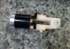
I came up with a (possibly) novel way to fix it, so I thought I'd share here.

This button is push-on, push-off, and the mechanism is external to the actual switch.

There is a nylon part with a pin. The back of the nylon part was broken, and I haven't seen any trace of the pin.

I made a pin from the stem of a pop rivet, using a drill and a sander as an improvised lathe.

I glued this to the remaining nylon with super glue.

It's really hard to glue to nylon, so there is no way it would stay there with just that.

I then re-constructed most of the missing nylon using more super glue and super glue "kicker".

I applied excess super glue, and using gravity, I got a drop to go where I wanted it, and then sprayed a mist of the kicker from a distance away.

The drop cured so fast it got hot enough to smoke, and probably partially melt the nylon.

I continued this until I basically "3D printed" most of the missing nylon.

I then ground the cured glue to the right shape with a Dremel cutting disk, and sanded it smooth.

I haven't put it all back together yet, but I tried operating the push button numerous times, and it seems OK.

The cured super glue is basically acrylic, so it's probably stronger (definitely harder) than the original nylon, and the heat should have been enough to bond them together.
 
Back
Top Bottom