• The move to the new server is done. There are some software and database maintenance updates in process. This has us passing the hat around to help out. We appreciate any donations. Seriously, even a dollar helps. The payment page may be found here - https://www.audiokarma.org/support.html

Is this a "Tape Head" input, or a "Line Level" tape input?

MonoMania

Member
Hello Audiokarma!

I'm restoring a Viking (department store brand) mono tube console from 1956.
Its a decent quality unit claiming "High Fidelity" with a push-pull 6V6 output stage and separate filament supply for the preamp.

I replaced all the electrolytic and wax capacitors and then connected a line-level source to the input marked "Tape". The result sounds unfocused and indistinct as if EQ has been applied.

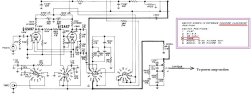
I suspect that I'm dealing with a "Tape Head" input, not a "Line Level" tape input... However... Schematics of multi-wafer rotary switches make me dizzy, and so after a couple hours staring at it I'm still confused about exactly what path the signal takes through the switch.

Could someone more knowledgeable kindly have a look at the schematic for the rotary switch and confirm my hypothesis?

If this is in fact a low-level "Tape Head" input then my goal is to permanently reroute it to become a line level input. Suggestions on how best to accomplish this (i.e. before the 'level' control?) would be welcomed.

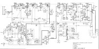
See attached schematic.
Thanks in advance!
test.jpg
 
Last edited:
Register to hide this ad
Yes ! Itza "tape head" input.
For reconnection, follow the radio input jacks. Is there a spare switch contact next to the radio radio input switch contact ?
Otherwise, you must change the new "Tape" input jack connection past the first 12AX7.
 
@tubeactive The radio signal comes into pin 11 on switch wafer "2F".
Adjacent switch contacts seem to already be in use.

I sure do get confused looking at multi-wafer rotary switch schematics...
Everything else on the page makes sense to me, except these.

Full schematic attached for reference.
 

Attachments

  • VIKINGFULLAK.jpg
    VIKINGFULLAK.jpg
    98.3 KB · Views: 8
Three clicks clockwise (into "Tape" mode) seems to send the signal from pin 4 to pin 8 of wafer "3F", which sends the signal onwards to pin 6 of wafer "4F" which makes no connection... Which would mean the signal carries on to pin 7 of wafer "2F" which seems to also make no connection... Which would mean the signal from 'Tape' input bypasses the 12ax7 entirely and goes straight to the 'level' control'... Doesn't it?

I'm pretty sure I'm just failing to correctly interpret the schematic.
Multi-wafer rotary switch schematics make my dizzy.
 
thats an odd way to do tape head. Most of the ones I'm familiar with feed it through the same path as the phono input. This one seems to skip the first gain stage.
 
@gadget73 Could you possibly tell me whether I'm reading the switch schematic correctly? I don't think I am... Which is why I'm here inquiring :) I assume that my interpretation above is wrong. Thanks in advance!
 
They give me a headache too honestly so I don't really know if you're reading it wrong or not.

honestly? I just tend to stick an ohm meter inside the unit with it set where it needs to be and confirm whats connected to what.
 
Deciphering the "schematic to real wiring" dilemma takes time.
I would need to see your actual unit, alongside reading the schematic.

Over and over, again and again I would watch the sequence and wiring from wafer to wafer, while checking the scheme. Eventually, our resistance readings and wiring path come to light the bulb inside our head.

The first two 12AX7 sections seem to serve the high gain/low level sources. Then again, your resistance readings indicate that Tape bypasses the high gain stages, meaning it already is set up for a line level input.

If that is true, simply insert a separate source like another tuner or a real tape deck's output or a CD opt to the tape jack.
Keep volume low while switching, so as to save ur speaker. You may have already figured it out...
 
Then again, your resistance readings indicate that Tape bypasses the high gain stages
I haven't made any resistance readings, those were just my attempt to interpret the switch from the schematic, and I probably got it wrong. I assumed that the veterans here would be able to make sense of the switch schematic at a glance, but gadget73 has implied that they aren't easy to read for anyone.

I will proceed with the advice given: I'll ignore the schematic and follow the signal path through the switch with an ohm meter - and then reroute the output of the switch's 'tape' position to wherever it needs to go.

Lesson learned: Don't waste time trying to make sense of multi-wafer rotary switch schematics.

just pull the 12ax7. If a source connected to the tape input works, its not running through that stage.
I'll try that first when I get back to it later today.
I shouldn't have been focused on the schematic when the switch itself is so simple.
As you pointed out, some thoughtful probing with an ohm meter will remove any confusion.

Thanks for all the advice! I profoundly appreciate this website and its community!
 
Conclusion: The schematic does show a line level input. The 'Tape' signal does not go through the 12AX7.

The audio problem turned out to be caused by a 6AV6 tube which wasn't making full contact with its socket.
Thanks to all who commented!
 
Back
Top Bottom