• The move to the new server is done. There are some software and database maintenance updates in process. This has us passing the hat around to help out. We appreciate any donations. Seriously, even a dollar helps. The payment page may be found here - https://www.audiokarma.org/support.html

Is this bad power transformer symptoms?

Yohan Ahn

Member
I have Sansui 8080 S/N 826090763

I got this about a year ago. When I got it, it was bought as a non working condition. I found a unit making very very low sound with a lot of scratching noises.

So I deoxit all buttons and pots but still not much improved. Couple months later I decided to start fully restoring 8080, using parts from ebay seller Peace.Love.And.Music, who sells vintage marant, Sansui, Pioneer stuff.

When I replaced parts I did DBT and made sure relay clicks everytime time I replaced parts for each board.

It was all going well with Power board, Amp, EQ, Protector board and so on... and when I was doing F-2543 tone control board it was difficult to figure out C607 and C611 caps location. It is very tight between each other and the service manual is not clear enough to see which hole goes which caps. So I did my best sense of knowledge and then I did not test DBT, just keep going replace two more caps on F-2545 filter & muting board.

After that I did DBT, but it did not click the relay anymore. I look through carefully again, F-2545 I can see very clearly no mistakes there. So it feels more like an F-2543 board that was a little confused by two caps hole locations.

Since I wrestling with that few days, nothing progress, always no relay clicks.

So I packed up and put it back on the shelf and did other things.

After a few months later I pulled out 8080 again trying to solve the puzzles. But no matter what combinations of those two caps, still no clicks at all. I also replaced two caps again, replaced whatever seemed odd, and measured every resistor's value, transistor, but NO Luck. So I started to trace out voltage checking from the power board. I saw there was a mismatched power voltage value from schematics.

Basically I found all wrong from transformer output voltages.

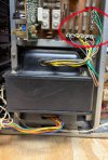
There are 10 wires output DC. I pull out a wire plug and DMM probe to measure each wires, all show few mV except white and grey wires.

Does this mean a bad transformer or I did stupid way to test again?

Please share any experiences
 
Register to hide this ad
Lots of fuses in your rig, both on the AC side and the DC side. Check them all with an ohmmeter.
Does it go into protection? (blinking lamp)
Unless you made solder bridge on the tone board that shorted out the DC feed, there is little to nothing you could do to the tone board that would trigger the protection circuit.
Can you set bias & offset?
 
Thank you for the reply.

Tutor_turtle; I checked all fuses and tested all good.

Yes It keeps protecting mode.

It can still bias and offset with protection mode. I can try that.


Robisme; At the transformer I measured DC volt on that wire's red circle. You mean the output on those wires is AC?
 

Attachments

  • IMG_5045.jpg
    IMG_5045.jpg
    141.9 KB · Views: 20
I measured AC volts on those 10 wires. Here is results

Color: measured value (Schematic value)

Yellow: 39.1V(38V)

Violet: 38V (44V)

Grey: 4.7V (1.4V)

White: 8.1V(Schematic only shows 0.1A)

Green: 22.6V(22V)

Brown:6.9V(6.5V)


It seems like mostly close enough except for Violet and Grey. Is it because maybe a 9090 value? One service manual for both 8080 & 9090

Thank you Jyrik. I didn't know that.
Im still don't know almost nothing about electronics, just doing this for my hobby.
 
I just tried DC Offset and Bias current.

When I turn the VR01,2 volt meter showing 0.2mv but DC offset won't change any.

Bias is worse.

remove fuse F07,8 DC voltmeter measured 50v and 60v and turn VR03,4 didn't change any values

I think it screws up bigger than I think.
 
If it is like almost every other Sansui, you measure amps (current) after removing fuses, not voltage.
 
Yellow: 39.1V(38V)

Violet: 38V (44V)

Grey: 4.7V (1.4V)

White: 8.1V(Schematic only shows 0.1A)

Green: 22.6V(22V)

Brown:6.9V(6.5V)

These AC voltage checks should each be as follows:-

Yellow to White - and White to (other) Yellow. (38V & 38V)

Violet to Grey - and Grey to (other) Violet. (44V & 44V)

Brown to Brown (6.5V)

Green to Green (22V)

Use the board pin numbers (on the schematic) to identify the coloured wires.


BTW How to identify model differences are noted on page 1 of the Service Manual, Model A = 9090 & Model B = 8080 - where there are differences it describes how they are indicated, 'in brackets' (for example) and quoting 'A' or 'B'.
 
If it is like almost every other Sansui, you measure amps (current) after removing fuses, not voltage.
Does that mean F07&8 50+V is normal? Now I see the service manual showing a little confusion. Model A(9090) is 50mV but model B(8080) is 30mA. So you mean service manual is error?

2026-04-02 160433.jpg


For Hyperion: Should I measure voltmeter two probes to test pin 4 and 6 for yellow to white. and 6 and 5 for white to yellow, is that correct?

I cannot see the model A and B transformer voltage difference from the service manual. I thought because my voltage came out lower than manual.
 
These AC voltage checks should each be as follows:-

Yellow to White - and White to (other) Yellow. (38V & 38V)

Violet to Grey - and Grey to (other) Violet. (44V & 44V)

Brown to Brown (6.5V)

Green to Green (22V)

Use the board pin numbers (on the schematic) to identify the coloured wires.


BTW How to identify model differences are noted on page 1 of the Service Manual, Model A = 9090 & Model B = 8080 - where there are differences it describes how they are indicated, 'in brackets' (for example) and quoting 'A' or 'B'.
I just tested voltage as your direction. it came out more likely service manual.
Yellow1 to white to yellow2 39V&39V
Violet1 to grey to violet2 38V&38V (this is questionable)
Brown to brown 6.8V
Green to green 22V
Thank you for saving me from big panics
Everyones helping makes my feels like oh gosh.... this is it

Now I need to measure F07&8 for mA
 
F07 shows 5.8mA

F08 shows 6.2mA

Both are not responding when I turn VR03&4

The DC offset is also not responding.

Anyone suggest what I should check this point?
 
Hi Olle

I found five BA312 chips across three different boards in this unit.

The same seller I purchased the restoration kits from also sells BA312 kits. Since these components are prone to failure, I believe it would be a good idea to replace all of them. I will order the kits while I continue testing.

Thank you for your reply.
 
I love that our intrepid gentleman is grabbing this bull by the pointy ends and getting elbows deep into this reasonably complex unit, but I fear that he is attempting to run before he can crawl. Don’t get me wrong - I spend 90% of my time in over my head, and the other 10% WAY in over my head. But an hour or two spent on YouTube watching videos regarding the basic principles of electricity and active and passive components may prevent a goring.
 
I love that our intrepid gentleman is grabbing this bull by the pointy ends and getting elbows deep into this reasonably complex unit, but I fear that he is attempting to run before he can crawl. Don’t get me wrong - I spend 90% of my time in over my head, and the other 10% WAY in over my head. But an hour or two spent on YouTube watching videos regarding the basic principles of electricity and active and passive components may prevent a goring.
Thank you for your reply.

I am currently taking lessons from YouTube and starting with the basics, right now specifically focusing on electronic grounding and linear power supplies in Sansui units.

I initially believed I could learn as I went, but I have found that vintage audio is far more complicated than I anticipated. I appreciate your guidance as I work through these fundamentals.
 
Hi everyone,

I managed to resolve one protection mode issue, but I’ve encountered a new problem.

To solve the initial protection mode issue, I removed the driver board and output transistors and powered the unit using a Dim Bulb Tester. I used a wooden stick to tap the solder joints on the boards; eventually, tapping a red wire on terminal 18 of the protector board triggered the relay. It appears the joint had become loose from flipping the board during parts replacement.

However, after reinstalling the driver board and output transistors, the DBT stays half-dimmed and the unit is back in protection mode. When I pull the driver board, the relay clicks and it exits protection mode.

I suspect this may stem from an accident a few days ago. While checking the DC offset and bias, I pulled fuses F07 or F08, and one fuse touched another fuse right below that causing sparks. I have checked all the fuses and transistors on the power and driver boards, and they appear to be fine.

I am currently stuck and unsure of how to proceed. Has anyone had a similar experience or suggestions on which parts are most likely to be damaged by that kind of short?
 
Man this is a hard one, parts swapping with the hope that fix something (horrible habit).
My diagnostics skills are mediocre to fair in a good day, and my time is limited but let's see.
after reinstalling the driver board and output transistors, the DBT stays half-dimmed and the unit is back in protection mode
Something is pulling current.
Protection means High offset.
Causes and something is shorted, unit is not adjusted correctly, something is installed wrong.

Read this and the service manual several times.

./ Try to post some decent pictures for visual inspection.
./ Do you know how to measure voltages?
./ Can you put smaller value fuses while you work on it?
./ What is the bulb size used on your DBT.
./ Be laconic and precise about the work and unit.

Let's go from there and see how it goes.
 
Last edited:
@Plimpington2, my first repair and restoration job was back in 1996 on a pretty rough 9090DB I paid 40 bucks for at an electronic junk shop. I wouldn't call that an ideal introduction to the art of restoring vintage hi-fi, especially as I had no formal training in electronic repair. And there was no real info or assistance online to aid in such endeavors then, as there is now. But somehow, I pulled it off. More than anything, I think one needs a certain structured mindset to approach this sort of work, and do it well.
 
@Plimpington2, my first repair and restoration job was back in 1996 on a pretty rough 9090DB I paid 40 bucks for at an electronic junk shop. I wouldn't call that an ideal introduction to the art of restoring vintage hi-fi, especially as I had no formal training in electronic repair. And there was no real info or assistance online to aid in such endeavors then, as there is now. But somehow, I pulled it off. More than anything, I think one needs a certain structured mindset to approach this sort of work, and do it well.
Well done, now let's see if the OP responds and we save this one.
 
Back
Top Bottom