• The move to the new server is done. There are some software and database maintenance updates in process. This has us passing the hat around to help out. We appreciate any donations. Seriously, even a dollar helps. The payment page may be found here - https://www.audiokarma.org/support.html

JBL James B Lancing SE400 schematic?

kanurys

Active Member
Hello all,

I'm recapping and updating an all-original JBL SE400. Every single electrolytic is leaking electrolyte. I've searched up and down and have failed to find a service manual or schematic for this amp. This unit has the eq boards you can flip around to bypass them. Not sure if that is a SE400 or SE400s.

Any info on this unit would be welcome. I found this old thread and posted a few comments there, too.
https://audiokarma.org/forums/index...-se400-before-sourcing-new-capacitors.865222/

Thanks
 
Register to hide this ad
I posted this in the old thread, reposting here. There's a service manual with a schematic for the SE400S here: https://www.hifiengine.com/manual_library/jbl/se400s.shtml

Axial caps are not as plentiful as radials but they exist. Capacitor values that exactly match what was used originally used. As another poster replied, you can always go up in voltage, and for PS filtering, up in capacitance to get to a standard value.
 
Thanks. I feel kind of dumb for not looking there for a schematic first. It never came up in my searches and I was lazy.

Yeah, a lot of older caps with non-standard values can be substituted with arrays, etc... Maybe I'll post some before/after pics here for fun. Thanks again.
 
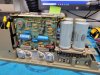
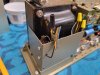
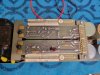
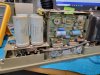
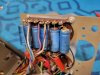
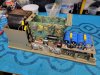
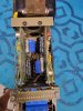
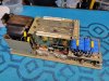
So here are a few pics of the original unit. I have all the info I need except I need help identifying that little silver cap on the EQ board. It states "470" and 25V and has a little red line on it (3rd picture). It's too small to be 470uF of that vintage, so I'm assuming it's pF but not sure; also is it an electrolytic?

20220804_113755.jpg 20220804_113801.jpg 20220804_113825.jpg 20220804_113844.jpg 20220804_114056.jpg 20220804_114101.jpg
 
Last edited:
Output stage layout looks very much like the JBL SA-660 I worked on a year or so ago. THe EQ boards are interesting, the 660 did not have those.

That one got a full set of small caps, didn't change the big ones. They were working and it was getting beyond the scope of what the owner wanted to be dealt with. It was here for a dead output channel, fixed that and found that many of the signal path caps were so shot that it simply did not work correctly. Replaced everything with axial types so it fit right, managed to find everything I needed but you get very few options in that package.
 
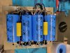
The SA-660 is a cool amp. This SE400/400S is really simple, but it's all very packed in. This harkens to some military design with it's integrated chassis and super hard grey paint. At least I can get to both sides of the driver boards without removing them just by pulling the EQ boards. The EQ boards are made to flip around to put them in bypass configuration - see the contacts on the ends. Just about every electrolytic in this amp is visibly leaking, but it still runs! The owner wanted to do all the electrolytics. There aren't many options for the big power caps and they'd rather have it safe to run than look perfect inside, so I think I'm going to install terminal strips and hang a few across the area where the old caps exist.
 
Also, the SA-660 looks to have the same power amp section and they just slapped on a preamp and put it in a larger chassis. The SE400/S had the EQ boards for a more permanent setting to work with various specific speakers. In the manual it looks like there was a range of EQ boards for various applications. Maybe the SA-660 was the more versatile unit.
 
The SA-660 had somewhat bad access, the way it was all mounted needed the screws in the middle of the chassis pulled and the whole thing split in half at the middle in order to be able to remove the output section driver cards. It didn't unplug either. It sounded pretty good but it was just awkward to deal with physically. The proprietary part numbers on everything also made working on it something of a guessing game. I found some old posts that gave me some (obsolete) crosses, and from there I was able to figure out some stuff but the output transistors I pretty much guessed at based on voltages and rated output power. Not like there are a ton of choices in TO-3 anyway. Basically everything ends up with one of a small handful of MJE numbers these days.

the lack of markings on the boards also made it somewhat more tedious to deal with. Had to be extremely careful to mark positions of everything as it came out in order to make it work again going back in.
 
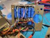
All done with the SE400. It came out wonderfully. All electrolytics were replaced. The power supply caps were upgraded - big caps after the main rectifier were increased in microfarads a little, all the 1000uF caps got a voltage increase. All rectifier diodes were replaced/upgraded. The electrolytics on the power amp boards were kept at exact values, but with a few combos and variations in voltage ratings to provide reliability. The signal caps on the input section were replaced with poly caps. I snuck a few caps on to the backside of the driver boards due to space appropriation. Here are the pics... Not the cleanest soldering and routing, but it is solid and sounds way better than stock. (yes, all the leads on the power caps got trimmed up...)
 

Attachments

  • 20220825_155822.jpg
    20220825_155822.jpg
    104.4 KB · Views: 13
  • 20220825_155836.jpg
    20220825_155836.jpg
    120.2 KB · Views: 12
  • 20220826_141708.jpg
    20220826_141708.jpg
    143.7 KB · Views: 12
  • 20220826_141724.jpg
    20220826_141724.jpg
    143.8 KB · Views: 12
  • 20220826_142344.jpg
    20220826_142344.jpg
    125.8 KB · Views: 13
  • 20220826_151533.jpg
    20220826_151533.jpg
    111.9 KB · Views: 17
  • 20220826_151614.jpg
    20220826_151614.jpg
    106 KB · Views: 13
Back
Top Bottom