• Please note that Audiokarma will be offline briefly for updates early on Monday morning, September 28th.

Just picked up a Sony TA-E77ESD preamp, and left channel not working?

That's not ideal, but something to think about. I wanted to integrate my new 2 channel system with my HDMI A/V receiver anyway, so I play around with using REC out and see how everything sounds. Would I'd still be getting the sound quality benefit of using this preamp if my A/V receiver is downstream and doing the volume control?

I believe the AVR would treat the REC out as another input and it'd go through the entire AVR chain, so you'd be putting it through a preamp twice. Also not ideal I think and would arguably defeat the purpose of having the Sony in the first place. A passive volume control is cheap though.
 
In the SM, they are marked RY followed by a number in the parts list, and marked the same on the schematics, with the circuit symbol being a rectangle with one diagonal line through the middle. Look at p27-28, middle and top, and you will find a slew of them, and then some trailing off to the right. That is probably most of them, but still a few more elsewhere, the ones with the higher RY numbers. To locate any on the chassis, you have to find them on the layout diagrams (the pages preceding the schematics) and/or then confirm on the boards by seeing the RY-number written on the board. They are unlikely to be on the underside of the boards. Once you find them, you can tap them.

As far as those in the middle of p27-28, they look to be double pole, as they are connected to both right and left channel. However, they seem to control the different inputs, and since your problem is with all inputs, including coaxial, it will not be them (they can't all be bad in the same exact way). The RY111-115 (trailing off to the right) might be involved, and same for RY116-118, which follow on to the right, showing in p.29, as I think these carry whatever signal is chosen by the input selector, but I can't confidently decipher the schematic right now because it is shorthanded for clarity and my skills are limited. Also RY601, 701, and 702 need to be found (if they turn out to be on the power board, don't worry about them).

 
In the SM, they are marked RY followed by a number in the parts list, and marked the same on the schematics, with the circuit symbol being a rectangle with one diagonal line through the middle. Look at p27-28, middle and top, and you will find a slew of them, and then some trailing off to the right. That is probably most of them, but still a few more elsewhere, the ones with the higher RY numbers. To locate any on the chassis, you have to find them on the layout diagrams (the pages preceding the schematics) and/or then confirm on the boards by seeing the RY-number written on the board. They are unlikely to be on the underside of the boards. Once you find them, you can tap them.

As far as those in the middle of p27-28, they look to be double pole, as they are connected to both right and left channel. However, they seem to control the different inputs, and since your problem is with all inputs, including coaxial, it will not be them (they can't all be bad in the same exact way). The RY111-115 (trailing off to the right) might be involved, and same for RY116-118, which follow on to the right, showing in p.29, as I think these carry whatever signal is chosen by the input selector, but I can't confidently decipher the schematic right now because it is shorthanded for clarity and my skills are limited. Also RY601, 701, and 702 need to be found (if they turn out to be on the power board, don't worry about them).

Wow, thank you for the detailed information. I will tackle this tomorrow and see if you are on the right track with regards to the relays
 
Not being cynical? if the option to return instead of a headache is open, I'd return it. imo.

It's not really a headache at this point, and if it turns out to be a simple fix it's definitely worth it as the price was less than half of what these usually sell for on eBay and it's a pretty well regarded unit. Nothing wrong with fixing a vintage piece and getting some more use out of it :D
 
I have had a chance to look at the circuit diagrams on a large monitor this morning, and can fill in some details (but please realize that I am, at best, an advanced novice at circuits, so if someone with more knowledge wants to chime in, please do).

After the input controls, the signal travels progressively through the Balance, Tone, Attenuator, and finally the Amp sections, where it gets routed to either the main outputs or the headphones.

The relays from RY113 through RY118 control that flow:

— RY113 inserts/removes the Balance control for the Left channel; RY114 does same for right. In your case, check RY113 as possibly faulty
— RY115 takes the Tone controls in/out for both channels

Signal next goes to the Volume (Attenuator) control and the Amp sections. After that:

— RY116 mutes both channels after the Amp
— RY117 and 118 are involved in the headphone circuit; they look like they disconnect the main output when headphones are used, and vice versa.

So I’d say your prime suspects are RY113, 115, and 116, as those occur after the input selector but before the headphone tap (because your headphone output is also affected). RY117 and 118 might also be involved as they switch the signal between the headphones and the main outs. Therefore all of the above are the ones I would try to tap while the unit is playing.

Locations:
On the layout diagrams, I see RY113, 114, and 115 on “Master VR Board” (between the p24 and p25 markers; look for the tag and the dashed box surrounding the relay rectangle and the contacts it controls). As that board has some Attenuator things on it, it could be a small board attached to the Attenuator pot.

R116, 117 and 118 are a little more difficult to see on the diagrams, but they are on the Main board, almost directly above the p23 marker (I guess above the 23.5 to 23.7 markers). Again, look for the dashed lines surrounding each relay and its contacts.

These locations on the layout diagrams should enable you to find the relays on your unit.

I did see RY601 on the Power board, but did not spot the RY70x ones. RY601 will not be your problem.

Edit: I guess I would add RY111 and RY112 in as well, as they control both left and right channels before the signal gets to RY113. They are located above the p23.4 marker on the layout board diagrams.
 
Last edited:
Not being cynical.. I mean it.. I chased a da333es amp for weeks after some butcher screwed up a lot of stuff.. got a nice str gx on the shelf in my line of repair. I'm a sony fan for the good stuff like the es lines.

I haven't looked at your SM however I do see similarity in many later designs by sony. (mini relays) I did find on a couple of similar units the ry's and the protect circuit was a total pita. one crummy lil .047 10v cap and zip nada. So went on and found a few caps for the relays were questioned.. lil transistors were fine just the caps didn't have the balls.

pretty sensitive circuits and the rail v's and any sub circuits the v's have to be pretty dead on or the transistors that switch on those small relays won't get juice enough or momma says via protect.. not going to fry speakers.

Northpaw has a good bead on things.. just adding v's need to be pretty good and god forbid your unit has some cheap plastic vr pots to adjust. might be worth replacing those. da333 had em.. good quality amp and they put that 10 cent piece of junk in the most important circuit to adjust to 5mv? stupid.
 
Thanks again @northpaw for taking the time to provide detailed info. I was able to find all the relays you referenced. Unfortunately, there is no change in output when tapping them pretty hard while music is playing. Is there a way to further test and see if the relay is the problem? This afternoon I will see if I can upload a video showing the problem and show the insides of the unit. Maybe visualizing it will help guide the next step?

@Binkman, it might be a lost cause, but like i said I like the unit and the price was good, so I'll give it a few days and see what happens. What are the vr pots? I don't see anything n the circuit board that allows adjustments, unless they're buried somewhere
 
Thanks for the relay testing info. But the relays on this are just black rectangles, do I need to access the bottom to find the leads or solder points? I should test them on the board not removed, right?
Here's a picture of one:
20161223_132228_HDR~2.jpg
 
ryuuoh has a good link if you take the relays out of circuit.

In circuit, the only other thing I could suggest is to cycle the relays while listening to music, to see if one of them is "wobbly", can be provoked to giving changing or otherwise inconstant sound.

Best way to proceed is to place balance to full left (so sound from the right channel doesn't mask things) and tone controls at their neutral positions. Then test each relay by activating and deactivating its switch numerous times, listening for changes in the sound of the left channel (comparing before and after each switching). Don't switch too fast; probably once every few seconds, comparing before and after. The first one to try would be the Adaptor In (whatever that is), and after testing that, Muting, then Tone in, and then Headphone, if that has a switch. If it does not, the switch is probably tied to the insertion of the phone plug into the jack in the front panel, so you would insert and withdraw and see if the sound is the same after one insert/withdraw cycle.

If there are not any changes that point to a particular relay, I'd say the problem probably lies elsewhere. I would recheck the cleaning of switches and especially the tone and volume pots. Failing that, I'd take the bottom cover off, get a magnifying glass and a good light, and look for cracked or otherwise dodgy solder joints. It is easy to reflow any that look suspect.
 
I just downloaded the owners manual for this, and it made me think that perhaps the left channel on the -20dB muting relay RY112 might have frozen contacts and it is muting the left channel whether activated or not. If your symptom is purely constantly low volume in the left without other wonkiness, then it could be the problem.

The thing is that: short of unsoldering it and figuring out what the default state of the circuit is with it removed (probably unmuted, but I am not sure of it), I don't know what to suggest to test it. Also, unsoldering it might make it difficult to return the unit, which is still your option if you can't get to the bottom of the issue.

BTW, the "vr pot" mentioned by Binkman above is probably "variable resistor pot", and could refer to one mounted on the front panel (volume or tone pots) or to an internal one on the boards, if any.
 
OK< I pulled the bottom panel off, and it looks to give me full access to all of the solder points, so I should be able to try some testing tomorrow :)

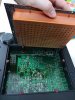
Here's a picture. Pretty interesting design by putting all the digital circuits in their own section totally encased in copper. I guess Sony was really worried about analog sound quality back then. Much different than some of my modern Sony AVR's I've opened up to fix...
20161224_211959_HDR.jpg
 
With that kind of access, you can measure the state of the relays (open, closed). Use the linked Panasonic document to see the pin outs.
 
Yes, I should be able to test them. Sorry for asking, but can someone give me quick run down of how to do that? What do I set my meter to? Which pins do I check with each red/black probe? Do I do this when the preamp powered off or on? If on, do I try and activate the relay while checking it? Sorry for asking such basic questions, but I'm still a newbie when it comes to this stuff. I'm not a total novice, I've installed MOD chips into playstations, build my own microphone battery box, built LED lighting systems, but usually I have instructions online. Any basic instruction will be appreciated :)
 
Put some electricians tape on your probes so just the very tip is visible. good light and you'll see your tips very clearly and tape prevents shorts accident in touching other solder joints.. accidents do happen in testing within close quarters. you can take a red marker pen to point the spots too.

Also take a good look at the soldering and a just a touch up of soldering on the relay. fast shot. cold solder joints and who knows maybe that relay was replaced by an equally bad one.. who knows.
 
First identify each relay's function, activating it from the front panel. Then, place your negative probe on chassis ground (a screw hole would do) set your multimeter to volts and measure the voltage on the relay coils. It should be somewhere near 12 volts. Verify each relay is getting about the same voltage. Next, Check the voltage on the common pins (still on chassis ground). With no audio signal, there should be no or very small voltage. If all that looks normal, measure ohms from the common pin to the NO pin, activating the relay. The meter should go from OL to some low ohms value.
 
Well I'm not entirely sure what happened, but I seem to have fixed it. One of this things I did was remove all the connected wire on the Master VR Board (where the volume knob is connected) and re-seated them. I also played with the volume knob some more turned it hard to the max a few times (I hit the stop a few times and was afraid of breaking something). I also removed and re-installed the Pin Jack Board (where the video & digital inputs are), but I doubt that had anything to do with it. So it was either re-seating the wires or messing with the volume knob that did something. I did play with the knob a bunch before when I cleaned it and it didn't help, so I'm leaning towards something with the wiring on the board? I don't know. It's been working so far all afternoon, although the problem re-appeared after I moved it to my main equipment rack. It started working again after cycling through a few inputs, so maybe there is an issue with a relay somewhere? It's so very frustrating not knowing for sure yet. Maybe I will still see if I can test the relays and see if anything is out off spec. I still have a few days before the return period ends (I also have the option of taking store credit for up to 30 days, cash refund only within 7 days).

Thanks again to everybody for your help and suggestions. You are awesome! I need to think hard if it's worth keeping it if the problem could reappear at any time.

If I do end up keeping it, I'll have to see if I can make some wood sides for it (they were missing when I bought it). Shouldn't be to hard, just need to find the original's dimensions...
 
Last edited:
Cable connections are a well known source of trouble, clean them up. Reseating a few times might wipe them clean, or a deoxit wipedown might do the job.
 
Back
Top Bottom