• The move to the new server is done. There are some software and database maintenance updates in process. This has us passing the hat around to help out. We appreciate any donations. Seriously, even a dollar helps. The payment page may be found here - https://www.audiokarma.org/support.html

JVC 4VR-5446 Stereo Receiver Help

V34Records

New Member
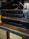
I recently acquired through a trade, a JVC 4VR-5446 Stereo Receiver from a local pawn shop. They had it for sale for $279.99. They couldn't get it to have sound. So I took a chance and traded in a couple of game systems and he let me take it home. It turns on fine, all lights come on, even FM Stereo when you get a good signal from tuner. Relay does not click. No sound. I've spent the last few hours testing a few different components. Every seems to be good. No bad caps, etc. I have noticed the fuse that's connected in the back on the receiver is a 2A 250V Fuse. It says on the receiver to use same type 4A-125V. I'm a noobie and I don't know much about fuses lol. Hoping someone else ran into this issue of no sound.

Front Left and right on Channel 1 give out 7.2mv
Rear Left and right on Channel 1 give out 0.6mv
Front Left and right on Channel 2 give out 0mv
Rear Left and right on Channel 2 give out 0.6mv


If there's anything I should check please let me know.

Thank you!
 
Last edited:
Register to hide this ad
Welcome to AK ! I have a 5444 and a 5445 but have never had to trouble shoot them, so I'm taking a shot in the dark here. Remove and check the filament in that fuse to see if it's blown (burnt filament like a bad light bulb). Put the correct fuse in. Too low it will blow, too high can cause damage. Make sure "tape monitor" is off if not using the input. My models are different, using separate equalizers for front and rear, but still similar. Check for a switch on the rear panel that controls speaker output and make sure it is set to ''norm" using just the front L and R channels. Best luck, you have a beautiful receiver. It seems unlikely a pawn broker would accept a non functional piece of gear, so hopefully it's something simple...
 
This thread reminded me how cool these old JVC units are. Mine keep getting ditched in line for a clean up and evaluation, undeservedly so. Looked at some selling on the auction site and am surprised how high prices are on 4VR quad models. Don't think anyone is buying... (?)
 

Attachments

  • 17169286744162909153017799868715.jpg
    17169286744162909153017799868715.jpg
    100.6 KB · Views: 10
Front Left and right on Channel 1 give out 7.2mv
Rear Left and right on Channel 1 give out 0.6mv
Front Left and right on Channel 2 give out 0mv
Rear Left and right on Channel 2 give out 0.6mv
where are you getting these readings from?

if you are measuring the speaker terminals, you are just reading residual dc since the relay has not closed.

you would need to measure the input side of the relay to see the dc voltage on each channel.

i am not familiar with the unit, just giving you a general tip.
 
where are you getting these readings from?

if you are measuring the speaker terminals, you are just reading residual dc since the relay has not closed.

you would need to measure the input side of the relay to see the dc voltage on each channel.

i am not familiar with the unit, just giving you a general tip.
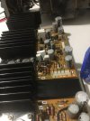
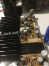
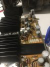
Upon further inspection. We have a cracked emitter resistor. Split right down the middle. Might replace all 8 of them and go from there.
 

Attachments

  • 31855C03-E258-459E-8936-B64543407F43.jpeg
    31855C03-E258-459E-8936-B64543407F43.jpeg
    95.4 KB · Views: 16
Looking to get some information on this MPC7 0.47ohmK resistor. Its clearly cracked in half and needs replacing. Wondering if I could replace those with a different style resistor or should I just stick with the same kind.

It was all burnt up at the bottom of resistor and left a mark on the board.

Edit: I am going to include schematics for this power amp. We are looking at R733. I just pulled this cracked one off the board. I see on schematics its says its supposed to be 0.22Ohms. All 8 of these resistors are .47 Ohms.


31855C03-E258-459E-8936-B64543407F43.jpeg2024-06-05 22_09_19-jvc_4vr-5446x_sm.pdf - Adobe Acrobat Pro (64-bit).png
 

Attachments

  • 31855C03-E258-459E-8936-B64543407F43.jpeg
    31855C03-E258-459E-8936-B64543407F43.jpeg
    95.4 KB · Views: 4
Last edited:
they don't just blow apart for no reason, you've got a shorted output and most likely other failed components. replacing that resistor won't fix it, it may go up in smoke tho.
Service manual calls for 0.22 Ohm 3W resistors. ALL 8 are 0.47 Ohm 5w that are installed. There are no other burnt up components. It’s the only one on any of the boards. I was going go replace caps and transistors as well on power amp.
 
Wondering if I could replace those with a different style resistor or should I just stick with the same kind.

I'd say that in this amp, you could replace them with any kind of 0.47 ohm resistors that will physically fit, and are of equal or greater power rating. I don't pick up any clues about power rating, though. I think you would be safe to choose replacements with 5W power rating. I think you should stick with the 0.47 ohm value. (Or 0.5 ohm, if those are easier to find.)

So much for the easy stuff. Forgive me if you already know this, but the resistor did not flame out of its own accord. It's almost certain that the output transistors (X713 and X715) are shorted. Even if they don't test shorted now, the same current that destroyed R733 almost certainly flowed through those transistors, so they shouldn't be trusted. By the same reasoning, R735 shouldn't be trusted.

Might be that the above is the end of the carnage. Might not. I suggest looking up and using a DBT (dim bulb tester), and not installing new output transistors until you're satisfied that the rest of the circuit is OK. The circuit should be able to mostly operate without the output transistors - it won't be able to drive speakers, but you can check with headphones.

Before you try even with headphones, though, make sure that the junction of (the newly replaced) R733 and R735 measures close to 0V DC. Also, make sure that the voltage measured between the emitters of the driver transistors (X710 and X712) is not much more than 1.1V.
 
There are 2 threads going for this same issue. Please continue in this one..
 
I'd say that in this amp, you could replace them with any kind of 0.47 ohm resistors that will physically fit, and are of equal or greater power rating. I don't pick up any clues about power rating, though. I think you would be safe to choose replacements with 5W power rating. I think you should stick with the 0.47 ohm value. (Or 0.5 ohm, if those are easier to find.)

So much for the easy stuff. Forgive me if you already know this, but the resistor did not flame out of its own accord. It's almost certain that the output transistors (X713 and X715) are shorted. Even if they don't test shorted now, the same current that destroyed R733 almost certainly flowed through those transistors, so they shouldn't be trusted. By the same reasoning, R735 shouldn't be trusted.

Might be that the above is the end of the carnage. Might not. I suggest looking up and using a DBT (dim bulb tester), and not installing new output transistors until you're satisfied that the rest of the circuit is OK. The circuit should be able to mostly operate without the output transistors - it won't be able to drive speakers, but you can check with headphones.

Before you try even with headphones, though, make sure that the junction of (the newly replaced) R733 and R735 measures close to 0V DC. Also, make sure that the voltage measured between the emitters of the driver transistors (X710 and X712) is not much more than 1.1V.
So before even discovering the cracked resistor, I already hooked it up to a dim bulb tester. No click of the relay but dim bulb flashes for a second and then goes out. So its showing no issue with power. Going to order a replacement resistor and see if that's the problem. I will end up rebuilding the whole circuit board most likely.

What would be a suitable replacement for this resistor?
 
Going to order a replacement resistor and see if that's the problem

Okay, my spidey sense is tingling - both from not catching on to what's happened with the duplicate thread business, but also from the seeming reluctance to accept that the resistor flameout is not "the problem". It's a problem, for sure, but not the problem. It's a symptom, not the disease. It's a victim, not the perp.

But here goes: Here's a probably-suitable resistor, picked from the last time I needed something similar:


That's an "axial" part with an 18 * 7.5 mm body. I expect you'll be able to fit it by "standing it up" (folding one lead over so that both leads point toward the circuit board holes). Do yourself a favor and order at least two.

When you replace the toasted resistor, you will find that the DBT will glow brightly. (At least it will if nothing else in the path of the disastrous current has gone completely open yet.) Then you can focus on the problem.

Sorry if I've been snarky. Please take on board that torched resistors are always a sign that something else is amiss.
 
i just repaired a nikko receiver. dim bulb dimmed yet it had 2 shorted outputs. it also had 2 open drivers which kept the bulb from seeing the short.
 
Okay, my spidey sense is tingling - both from not catching on to what's happened with the duplicate thread business, but also from the seeming reluctance to accept that the resistor flameout is not "the problem". It's a problem, for sure, but not the problem. It's a symptom, not the disease. It's a victim, not the perp.

But here goes: Here's a probably-suitable resistor, picked from the last time I needed something similar:


That's an "axial" part with an 18 * 7.5 mm body. I expect you'll be able to fit it by "standing it up" (folding one lead over so that both leads point toward the circuit board holes). Do yourself a favor and order at least two.

When you replace the toasted resistor, you will find that the DBT will glow brightly. (At least it will if nothing else in the path of the disastrous current has gone completely open yet.) Then you can focus on the problem.

Sorry if I've been snarky. Please take on board that torched resistors are always a sign that something else is amiss.
Not snarky at all lol I appreciate it actually. So I tested the resistance with all of my output transistors and I got resistance on all of them EXCEPT X713 and X715. Just like you thought. They are 100% shorted. I am putting together a parts list with everything. I am going to rebuild the whole board, upper and lower channels. I just need to find replacements for these output transistors. They are a Sanken 2SC1445 and a Sanken 2SA765 combo for this channel. To-66 body style. They seem quite hard to find. Any good ideas on replacements for these? I see a lot of "knockoffs" online.
 

Oh, shoot, hadn't noticed that. That makes things a little difficult. I think the safest thing is to replace them with TO-220 parts. The TO-220s' base and emitter terminals will have the same separation as TO-66, but you'll have to bend those terminals so that they point down to the circuit board. You might even need to extend the leads somehow, if they're not long enough, and in any case make sure they don't touch the heat sink. You would cut the middle lead (the collector) short, since its connection will be made by the screw through the tab. Oh, and you'll need some insulating wafers made for TO-220s.

If you're game to go with TO-220s, I think MJE15028 (NPN, for the 2SC1445 position) and MJE15029 (PNP, for the 2SA765) would be good choices.

Whether TO-66 or TO-220, it can be helpful to defer the installation of the screws - that is, leave the collectors unconnected - the first time you try powering up under the DBT. At that time, make the voltage checks mentioned above. The idea is to make sure the base and emitter voltages are sane, while preventing any large collector currents that might happen if something else is amiss.

I've probably forgotten something, but hopefully this is enough to go on, and/or someone will be along to say what I've missed.
 
Hmm, I just noticed that one of the ebay sellers of 2sA765 and 2SC1445 is ceitron. I trust them (Consolidated Electronics) to not knowingly sell fakes. Prices seem fair to me.
 
Back
Top Bottom