• The move to the new server is done. There are some software and database maintenance updates in process. This has us passing the hat around to help out. We appreciate any donations. Seriously, even a dollar helps. The payment page may be found here - https://www.audiokarma.org/support.html

JVC AX-R97 sound issue

pioneer07

Member
I am wondering how screwed I am here. I snagged this AX-R97 for $30 on marketplace. It needs some work. It has that nice display on the front but the fuse lamps were burnt out. I've replaced fuse lamps in 1 other JVC receiver and I was aware some diodes likely got fried when the lamps burnt out. For the heck of it, I did just try replacing ONLY the lamps, but they didn't turn on. I dug a little deeper and there are at least 5 diodes that got fried (D812, D815, D831, D832, D833). There was also a resistor (R843) that partially crumbled when I touched it.

What I did with the other JVC when I replaced the fuse lamps is I just removed the diodes and ran the lamps in series, and that worked. So that was my plan for this one. Here is the thread about that other JVC.

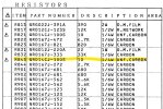
R843 is the main resistor right in front of these fuse lamps that cumbled. The manual says it is "10 UNF Carbon 1/4 W". I was like, oh, I have a 10 ohm resistor that's rated well over 1/4 watt. I removed all the burnt out diodes. I also lifted the center connection between the lamps and left that open to make it a series circuit. And of course replaced the R843. The lamps briefly came on. Then I got a little smoke and quickly shut it off.

I'm very confused what this R843 resistor is supposed to be. The bad resistor measured about 280 ohms. I figured that number was totally unreliable since it was so damaged. The colors on that old resistor are 5 band, and it looks like white-red-black-black-silver (920 ohms??? or are they using an older version of the colors?).

Prior to this, I was getting 37 volts at the right side of that R843 resistor (which looks correct per the schematic). Afterwards, I'm getting -0.4V. That means transistor Q802 is also likely cooked. Worse, when I tested out the unit again, there is distortion that was not there before. The concern now is a current or voltage spilled into another area of the circuit and damaged something else. Is there hope for this unit? I'm not going to do much more work on it if you tell me that I fried some hard-to-find IC chip or something.

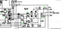
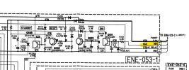
Here's a link to the service manual and a screenshot of the part of the schematic with the fuse lamps, and what it says for R843.
 

Attachments

  • Screenshot 2024-11-25 220453.jpg
    Screenshot 2024-11-25 220453.jpg
    249.1 KB · Views: 6
  • Screenshot 2024-11-25 222229.jpg
    Screenshot 2024-11-25 222229.jpg
    197.5 KB · Views: 6
Register to hide this ad
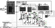
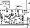
I checked a lot of voltages. See attached screenshots. On the main power supply board (ENH-122-2) there are 2 voltages measuring low, they are on either side of D826. The 11.8V is measuring only 4.8V and the 11.2V is measuring 6.7V. All other voltages on that board are good. I'm guessing this is an issue, but not sure it's "the" issue.

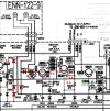
The voltages coming into the main amplifier board are also all good as shown. All voltages at the "Protector" are OK (not shown in the pictures but I did check them).

The voltages in the areas where the burnt out diodes and R843 used to be are all measuring close to zero.

I did try checking the other board that gets voltage from that area where the burnt out diodes were. The 5 pin connector where it says "EQ ANALOG DW P SUPPLY" . I checked the voltages at analog switch number IC902:
  • Pin 1 was supposed to be -15.2 measured -15.5
  • Pin 14 was supposed to be ground and got 0V
  • Pin 15 was supposed to be 4.5 (I think, hard to read) but measured 0.1V
  • Pin 28 was supposed to be either 4.7 or 14.7 and measured 0.1V
These could be off since I don't have R843 or the diodes in there at the moment. That's all I've checked on that board so far.

I also checked voltages at about a third of the transistors on the rest of the main amplifier board (the ones nearest the burnt diodes) and have not found any other voltages that are off.
 

Attachments

  • Power1.JPG
    Power1.JPG
    92.9 KB · Views: 6
  • Power2.JPG
    Power2.JPG
    71.3 KB · Views: 4
  • Power3.JPG
    Power3.JPG
    79.2 KB · Views: 5
On the first diagram they gave the voltage listed right at the transformer. I think that should possibly be on the other side of diode D826. So, I would check that diode and solder connections.
 
D826 looks fine and so do the solder connections but I could always replace it easily. Those voltages that are not measuring right are coming off of the second smaller transformer T002. The voltages for the main amplifier come off of T001. Those are captured in the second screenshot, and they all looked good.

I think I'm going to order a D826, the other 5 diodes that burnt up, and 10 ohm resistor to replace R843, and put them in and see what happens. I'm just not really seeing many issues in this part of the circuit other than where parts are missing. I'm worried the issue could be on that other board, I think its ENE-053-1. It's the one there that analog switch is. The reason I point that out is because that board is where the inputs come in, and it's directly connected to the area of that R843 resistor. I was using the CD input when I had the issues. I could try a different input for the heck of it and see if it has the same issue, but they all go through an analog switch. But if that circuit is getting voltage from this other one too and I have missing parts then it may be impacted too.
 
I replaced those 5 burned up diodes and also R843.
Good news: sound is back to normal.
Bad news: the fuse lamps are still not lighting up.
Whatever was damaged must have been in that part of the circuit. If anyone has something easy to try, I'd be open to it but otherwise I think I'm going to take the W and leave well enough alone.
 
Spoke a little soon. There may be a minor sound issue. It's not noticeable at low volume. At higher volume there is just a little distortion at certain frequencies. You notice it on certain vocals. Most frequencies sound fine. As I'm typing this, it appears to have gone away.

I just got this one and I had not put it through the paces very much yet. It's possible this issue existed prior to me messing with it, and I just hadn't used it enough to notice it yet. (or maybe it hadn't happened yet). I haven't replaced any capacitors in this unit yet.
 
Make sure C823 is not leaky (electrically) or shorted.
I will check this, but this part of the schematic has me baffled. Maybe someone can enlighten me. The power circuit on the schematic shows 11.2V at the "INH" line on the connector. But if you follow where that connector goes to (attached), it only shows 5.4V at that point. What gives? I was measuring 6.7V, which is a bit high compared to 5.4V but I'm confused about which is correct.
 

Attachments

  • Screenshot 2024-12-03 002706.png
    Screenshot 2024-12-03 002706.png
    182.5 KB · Views: 7
No idea. Mistake on the schematic. As for the lights not working.. Is there a cracked or burned PCB trace?
 
No idea. Mistake on the schematic. As for the lights not working.. Is there a cracked or burned PCB trace?
I will take a look the next time I open it up. The area where those diodes failed is definitely burned up a bit, but I haven't checked continuities yet.
Do y'all think that re-capping will help that minor distortion issue?
 
Do y'all think that re-capping will help that minor distortion issue?
Only if it is a failing cap. Maybe the speaker protection relay needs to be cleaned or replaced. It could be a dirty switch or pot if any are mechanical. It could be a faulty transistor or anything else. Did you check the bias? Do so very carefully with mini grabbers. Do not adjust anything without knowing what you are doing! Turning the bias up too far can blow the output transistors and whatever else goes with it during a cascade failure..
 
I have not adjusted anything yet, and I don't usually mess with bias. I will clean switches, pots and replace some caps. And if none of that fixes it I will start trying to see if there are transistors or other things that could be bad. I just haven't had this particular issue before of distortion. The most common issues are either one side too quiet compared to the other, or one frequency range too quiet compared to others. I haven't had this kind of weird thing before where only certain tones at certain volumes sound kind of scratchy.
 
Did a little more checking on this one. Continuity around those diodes that I replaced all checks out good. All the connections are how they are supposed to be.

Bad news is the voltages at Q801 and Q802 are way too low. All voltages at the base, collector and emitter on these two are measuring 0.4V (except emitter at Q801 was 0.6V).

The voltages at the nearby Q803 are all correct.

When I was taking these measurements I got some more smoke. Hard to tell exactly where its coming from and I don't see anything obviously burnt yet. I turned it off quick again. I had the bottom of the board towards me when this happened but my best guess is the smoke may have been coming from another board, the one that connects to this area of the board via connector FW805. The voltage B+ from that board connects directly to Q801. I just checked R361 and R362 on that other board and they look OK and measure 68 Ohms, which is what they are supposed to be. Again, I can't see anything that is obviously burnt yet.

I should mention that when this happened the fuse lamps were not in the unit, if that matters. I had to take them out to measure continuities and I haven't put them back in yet.

This is wild to me because I actually listened to this unit for like an hour the other day to get familiar with this sound issue. No smoke for that full hour. At that time I did have the fuse lamps in place if that makes that huge of a difference. I also wonder if the act of checking voltages might not be a factor here. I noticed the smoke when I was measuring the (correct) voltages at Q803.
 
Did the diodes short again? Do not run without fuse lamps in! Maybe a dim bulb tester is in order?
 
No the diodes did not short again. With the fuse lamps in there, voltages at Q801 and Q802 are even less, close to zero.

I think I know why the diodes didn't short. I found a cooked resistor - R803 is visibly fried. I haven't lifted one side of any of these resistors to get an exact measurement, but my understanding is leaving them in the circuit might give you a lower measurement, not a higher one (since stuff might be in parallel with it). As it is in the circuit, R803 is measuring way high. It's supposed to be only 4.7 ohms and it's measuring about 3K. Clearly cooked.

I also checked R801 and R802. They don't seem to be visibly damaged, but who knows. Those are both supposed to be 110K ohms but R801 is measuring about 500K and R802 is measuring 1400K.

R809, R810 and R811 are in parallel and are spot on. Each are supposed to be 270 ohms, or 90 ohms combined in parallel. That's exactly what I got.

R843 is the one I just replaced and it's still fine

I think I'm going to replace R801, R802, and R803 and see what happens. Does this seem like a sane course of action? Anything else I should consider replacing while I am at it?
 
R801 and R802 are bleeder resistors across the main filter caps. If you are measuring in circuit, the readings will be off.
R803 is a unflammable 1/2 watt resistor. If it's cooked / open. there is / was a short in that circuit.
 
I did a lot of work on this one. I replaced Q801, Q802, a few more resistors, and the electrolytics in this part of the circuit. Then I also checked everywhere for continuity and shorts to make sure I didn't find anything weird. Success. The fuse lamps now light up and the weird little bit of distortion that was left also appears to be gone. I did notice the volume pot was just a little scratchy. I will clean it at some point. There's probably more electrolytics that could be replaced but I'm leaving well enough alone for now.

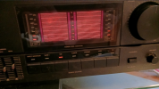
I was hoping this big display would do a little more than this but it still looks pretty cool.
 

Attachments

  • Screenshot 2024-12-20 191619.png
    Screenshot 2024-12-20 191619.png
    617.2 KB · Views: 6
This unit is still working fine and sounding fine. I just noticed something odd about it though. I get a small static shock when I touch the metal case. Nothing big, similar to a small shock you might get from a metal doorknob. I tried measuring to see if it had a voltage on it. It looks like maybe 0.25V AC is on it? It's hard to say because it fluctuates a lot. Is this anything to worry about?
 
Back
Top Bottom