Beavs
Active Member
Need some help as the amp won't come out of protection mode and my troubleshooting knowledge has a long way to go.
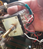
Got this amp knowing that the left channel was out. Turned out to be the same issue others have had with the wire connection to the volume pot (see post #5 here: https://audiokarma.org/forums/index.php?threads/jvc-ja-s71-right-channel-out.807344/). Solder connection was fine but the left channel wire snapped at the solder joint and was loose (see white wire in pic, should connect to 2nd pin from bottom). Soldered the wire back to the pin and both channels were working now.
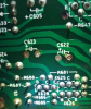
Then I went to set the idling current and DC offset per the SM. Idling current was no problem, but the left channel would not go lower than about 200mv. Did some inspection/measuring for components around the trimpot VR601 and turned out that diode D603 was shot. Replaced D603 and DC offset was set per the SM and everything was looking to work fine.
Hooked the amp up and let it play for the day. Then day 2 came and had been playing it for a couple hours when my wife paused the music because of a work meeting. Amp was left on but no input feeding to it. Few hours later I went to start the music again and no sound. Turned the amp off and then back on and the protection relay wouldn't engage. I've been testing components around the relay as well as the power supply and everything seems to be measuring fine as far as caps, resistors and diodes. Haven't pulled any transistors yet. Odd thing that I'm seeing is the voltages on the power supply board.
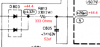
Voltages seem to be within the ballpark until you get to Pin 9 but the R813 and C805 seem to measure fine...just not getting the expected voltage drop from D803 listed voltage to Pin 9 listed voltag. Image pasted below or PDF attached for measurements I'm seeing. Any help on where to go from here would be appreciated.

Got this amp knowing that the left channel was out. Turned out to be the same issue others have had with the wire connection to the volume pot (see post #5 here: https://audiokarma.org/forums/index.php?threads/jvc-ja-s71-right-channel-out.807344/). Solder connection was fine but the left channel wire snapped at the solder joint and was loose (see white wire in pic, should connect to 2nd pin from bottom). Soldered the wire back to the pin and both channels were working now.
Then I went to set the idling current and DC offset per the SM. Idling current was no problem, but the left channel would not go lower than about 200mv. Did some inspection/measuring for components around the trimpot VR601 and turned out that diode D603 was shot. Replaced D603 and DC offset was set per the SM and everything was looking to work fine.
Hooked the amp up and let it play for the day. Then day 2 came and had been playing it for a couple hours when my wife paused the music because of a work meeting. Amp was left on but no input feeding to it. Few hours later I went to start the music again and no sound. Turned the amp off and then back on and the protection relay wouldn't engage. I've been testing components around the relay as well as the power supply and everything seems to be measuring fine as far as caps, resistors and diodes. Haven't pulled any transistors yet. Odd thing that I'm seeing is the voltages on the power supply board.
Voltages seem to be within the ballpark until you get to Pin 9 but the R813 and C805 seem to measure fine...just not getting the expected voltage drop from D803 listed voltage to Pin 9 listed voltag. Image pasted below or PDF attached for measurements I'm seeing. Any help on where to go from here would be appreciated.