• The move to the new server is done. There are some software and database maintenance updates in process. This has us passing the hat around to help out. We appreciate any donations. Seriously, even a dollar helps. The payment page may be found here - https://www.audiokarma.org/support.html

JVC JR-S401 Output Transistors Replacement

FRANKPIETTE

Member
Hello everyone,

I have that JVC that the output transistors D736/B700 HPAK case. I looked for a replacement so far nothing or equivalent hard to find. Any help would be very appreciated.

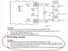
There's only 1 trimmer per side but 4 measuring points per side. I adjusted X723 idling current at 10mV then i measured at X721 10mV, then X725-727 were way out and negative values, same behavior on the other side.

So i'm looking for the best equivalent output transistors, anyone ever faced that behavior ?

X723 10mV right on the nose
X721 10mV
X725 -9mV
X727 -9.6mV
 

Attachments

  • JVC.JPG
    JVC.JPG
    66.2 KB · Views: 6
Last edited:
Register to hide this ad
9.6mV is within specs if your goal is10mV.

The "-" sign just means that you have reversed the black and red probes.
If the circuit is reacting to the adjustment, 9.6mV instead of 10 is OK in my book. If it's fixed at 9.6mV and not responding to the adjustment, you need yo investigate further.
 
Hello Elnaldo, according to the service manual the black probe seems to be on the ''Out'' post, and the red one for all four posts per side. But i might be badly interpreting the image. Thank you wish you were spot on. I might be spot off or an error in the serv. manual?
 

Attachments

  • Idling.jpg
    Idling.jpg
    101.1 KB · Views: 3
The 2SD736 is an Hitachi "HPAK" package. It's got the same 24.4mm bolt-spacing as MT-200, but it's quite a bit smaller dimensions, 32x15mm, versus MT-200 at 36x21mm. If your heatsink has the room, MT-200 replacements should work.

However it doesn't sound like your issue is actually the output transistors. Usually bad outputs will cause more dramatic issues than bias offsets.
 
Hello Elnaldo, according to the service manual the black probe seems to be on the ''Out'' post, and the red one for all four posts per side. But i might be badly interpreting the image. Thank you wish you were spot on. I might be spot off or an error in the serv. manual?
We need to see a schematic to see what those Tests points actually are. I guess the +- sign is normal and not an issue, but a schematic is needed to confirm or discard this.

I bet the test points are at the positive and negative emitter resistors, making that "+-" a normal reading.
 
Back
Top Bottom