• The move to the new server is done. There are some software and database maintenance updates in process. This has us passing the hat around to help out. We appreciate any donations. Seriously, even a dollar helps. The payment page may be found here - https://www.audiokarma.org/support.html

JVC QL-A2 DD that plays: Hooouuuuuteeiiiiiiiillll Caliiifooouuuuuurniiiaaaaah

Dr.Turner

Active Member
Hello everybody,
last week a friend gave me his JVC QL-A2 turntable with speed issues: wobbling sound and no strobe light.

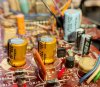
Inspecting the board showed a couple of leaking capacitor and two broken diodes (probably from the leak-glue hotmix) in the PS: "piece of cake" I thought “replace the components + deoxit speed switch" (a common solution found pretty everywhere for “speed issue" and "QL-A2” search).
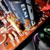
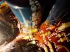
leak1.jpg leak2.jpg

I was wrong.
Oh, how much I was wrong! After a week of head banging on the board still "Uoouooo-teeeell-Caaaliff-uuuooo-rniaaa-suuuucchaaa-luuoooovlyyplace” from the test vinyl!
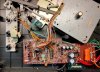
open.jpg
 
Register to hide this ad
What has been done so far:

1st wave
  • removed the motor to check for mechanical interference, it was clear of debris, smoothly spinning
  • deoxy all switches and VR801 and VR802 (for 33/45 RPM fine tuning)
  • replaced the leaking capacitors C822-C823
  • replaced diode D809 (RD5.6EC) with 1N5232B
  • replaced diode D803 (1S2473) with 1N4148 as suggested by avionic and EchoWars here
  • since voltage at TP5 was less than 20V I adjusted VR803 to have 22V. I naively hoped that putting correct voltage on point “h” (emitter of voltage regulator X815) would solve the problem...but...not.
= still wobbling
 

Attachments

Last edited:
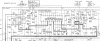
Your schematic is too blurry to read, See a high res version below.
1. You need to be clear about the symptom: is it running slow, or the correct speed but varying?
2. Do you have a scope?
upload_2022-10-4_11-54-56.png
 
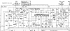
Here's the part we will be concerned with:
upload_2022-10-4_12-3-19.png
 

Attachments

  • upload_2022-10-4_11-59-38.png
    upload_2022-10-4_11-59-38.png
    318.9 KB · Views: 14
2nd wave
  • I replaced other electrolytic capacitors (C817, C819, C821) and the three 2SC945 transistor on the PS with KSC945GTA crossing legs since the sub is E-B-C and protecting base with heat shrink tubing
  • No way to have 5.22V on X814 emitter --> impossible to feed the oscillator/frequency divider (IC802) with correct voltage...
= still wobbling

subs1.jpg
 
Thanks dr*audio, yes I realized the picture was blurry and I've uploaded the .PDF
And, yes, I have a scope: your approach is going staight to the point without much care to the voltages!
 
Last edited:
The speed is changing during play, with a wobble effect.
Now that I replaced the bridge rectifier also, I'm checking it again with the same Hotel California test vinyl and report in a flash.
 
This is the wobbling problem, with a standard A test tone (440Hz - 0,1% accuracy) played at 33rpm and 45rpm.

 
Remove the platter and see if it's stalls at 33 and a third. If it stops that means that there's a bad poll in the motor. If it doesn't stall with no platter then it's a stability problem and you should adjust the PLL adjustment I think it's VR 801.
 
I'm pretty sure that if I remove the platter the motor does not stall, since all the test were all conducted upside-down without the platter.
I've already used deoxit on VR801 and VR802 and they DO affect speed at 45rpm and 33rpm.
 
I'm pretty sure that if I remove the platter the motor does not stall, since all the test were all conducted upside-down without the platter.
I've already used deoxit on VR801 and VR802 and they DO affect speed at 45rpm and 33rpm.
I need you to check it, I need to eliminate a bad pole in the motor before continuing troubleshooting the PLL.
 
Removing the platter does not stall the motor, neither at 33rmp nor at 45rpm (BTW why you suspect a motor stall when you remove the platter? Platter is weight=load and stall happens when there is so much load the motor stops and torque is max).

Anyway the motor does a regular, rhythmic sound when spinning: see video, it is clearly audible over the background noise (please note I have amplified the audio track, so the BG noise).
This rhythmic sound is NOT there if:
  • you crank all the way up VR801 and VR802 (obviously the motor is spinning at much more than 33rpm and 45rpm)
  • you spin the rotor by hand, slow or quick (this excludes mechanical obstacle or friction)
 
Last edited:
1. The platter acts as a flywheel to store momentum and keep the motor turning between the push of each pole. If one pole of the motor is out, it will stall between the poles with no platter.
2. You say you don't hear the clunking sound when you turn the motor by hand so I think we can rule out mechanical interference.
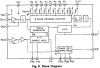
3. Connect your scope to pin 4 of the PLL IC (TP3). You should have a waveform here with decent p-p amplitude, like 4V. See if it shows the speed changing; it should since it's the FG pulse. Post a picture of it.
4. Confirm that you can see the crystal frequency at pin 2 or 3 of the PLL IC. I would expect at least 1V p-p on one of the pins.
The PLL IC requires a crystal reference and a good FG signal to work correctly. If the FG signal has noise on it or drops out, the IC will put out erroneous pulses on the correction voltage.
5. C816 filters the correction voltage. If it was bad, it could cause pulsing.
 
1. The platter acts as a flywheel to store momentum and keep the motor turning between the push of each pole. If one pole of the motor is out, it will stall between the poles with no platter.

That's the beauty of fixing an hi-fi, you're always at school! Thanks for the explanation.
Now I'm looking for the 'scope, we have recently moved and it's stashed in some box.
Later.
 
One more thing to look at. It is possible that one of the motor coils is loose and hitting the magnet when it is energized. Remove the rotor and inspect the area underneath.
 
Unfortunately I found the Rigol digital scope first, which I don't like (I was hoping to find the analog Tektronix 2465...next time).

Please review the video of pin 3 and pin 4 as suggested.
Measurement as shown: crocodile on TP2 and probe on TP3 or IC pin 3.

probe.jpg


Pin 4:
the Vpp is 4.5V but the frequency fluctuates alot.
Video showing 33rpm ("around" 50Hz), but responds to 45rpm switch also, loosly centering around 67Hz...


Pin 3:
The crystal freqency is nearly there...not steady locked

 
Last edited:
Ok, now look at pin 11 of the IC, that's the correction voltage. Should look like a PWM waveform and it should have a varying pulse width.
Then look at C816 with the scope. It should be a varying DC voltage. Post a picture. If it has a lot of ripple, I'd replace C816.
 
Thanks dr*audio,
I will be able to be at the bench again as early as tomorrow afternoon.
 
Last edited:
Back
Top Bottom