• The move to the new server is done. There are some software and database maintenance updates in process. This has us passing the hat around to help out. We appreciate any donations. Seriously, even a dollar helps. The payment page may be found here - https://www.audiokarma.org/support.html

JVC RX-503BK Blown Channel, But WHY...?

Troy Kilian

New Member
Hey folks so I have this old JVC stereo receiver that has been sitting around for years because the main fuse kept blowing. So I finally took the time to investigate and surprisingly I found that the output transistors on the left channel were blown. Now I really have no idea what I'm doing and am a complete newbie at this so I need the collective help from all of you geniuses on here. If you guys don't mind, it would be so appreciated! After I found the left output transistors blown I pulled them out replaced the fuse and powered the receiver up just fine. Hooked up an audio signal and got output audio through the right channel on a speaker. So I figured the short had to do with thermal overload and thought I could just replace the output transistors and be on my way. I was lazy and just found NTE's as replacements instead of the original SK's (plz don't call me dumb I didn't know what I was doing at the time) and those blew out too. So I'm not sure where else the problem could be. Was it just the shitty replacement transistors I used or is the problem somewhere else? I've checked many transistors verifying that they are okay and I also checked the emitter resistors and those are okay too. I have a service manual you guys can check and show you what I have gone through so far. http://freeservicemanuals.info/en/servicemanuals/download/JVC/rx-503bk.pdf
 
Register to hide this ad
The main reason why the fuse would blow would be a short - usually either in the outputs or bridge rectifier - so this isn't suprising. Outputs can be blown by such things as shorting the speaker wires on that channel and the protect circuit (if there is one) doesn't work for some reason to protect the outputs.

The fact that you replaced the outputs with NTE parts doesn't automatically mean those parts were faulty, which led to them blowing again. You are more likely looking at a continuing fault that hasn't been rectified "upstream" - say possibly with the pre-derivers - that will keep causing the outputs to blow.

I would recommend a couple of things. First, build a dim bulb tester (instructions are on this site to do that), second, ensure you have the right equipment - good soldering iron, solder, digital meter. Third, find and download a service manual. I would recommend pulling the drivers in the faulty channel and testing them too.
 
The main reason why the fuse would blow would be a short - usually either in the outputs or bridge rectifier - so this isn't suprising. Outputs can be blown by such things as shorting the speaker wires on that channel and the protect circuit (if there is one) doesn't work for some reason to protect the outputs.

The fact that you replaced the outputs with NTE parts doesn't automatically mean those parts were faulty, which led to them blowing again. You are more likely looking at a continuing fault that hasn't been rectified "upstream" - say possibly with the pre-derivers - that will keep causing the outputs to blow.

I would recommend a couple of things. First, build a dim bulb tester (instructions are on this site to do that), second, ensure you have the right equipment - good soldering iron, solder, digital meter. Third, find and download a service manual. I would recommend pulling the drivers in the faulty channel and testing them too.

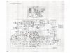
I have all of that equipment other than the dim bulb tester because I didn't find a necessary use for it yet. I have also pulled and tested many of the drivers so far (so I think). I scanned a circuit diagram from the service manual and marked with red every transistor I have checked out as okay so far. Let me know what you think.
 

Attachments

  • JVC 503BK Circuit Diagram 300DPI.jpg
    JVC 503BK Circuit Diagram 300DPI.jpg
    89.6 KB · Views: 7
I have all of that equipment other than the dim bulb tester because I didn't find a necessary use for it yet. I have also pulled and tested many of the drivers so far (so I think). I scanned a circuit diagram from the service manual and marked with red every transistor I have checked out as okay so far. Let me know what you think.

This is a link to that scan with a higher res so you can see it much better... https://www.dropbox.com/s/hjvxelzymz2af53/JVC 503BK Circuit Diagram.jpg?dl=0
 
So you have been testing transistors in the good or bad channel? Looks good so far, carry on....

Just testing in the bad channel. Could there be an explanation to why all the other transistors upstream in the signal path are okay but for some reason only the outputs are blown? The emitter resistors re okay as well. I just can't understand why only the output transistors are blowing.
 
So the NTE outputs you put in were definitely the same polarity as the old ones?

I may leave someone more knowledgeable to chime in here but perhaps try building your DBT then power up the amp with the outputs on the bad channel removed and see if the bulb glows brightly.
 
Back
Top Bottom