• The move to the new server is done. There are some software and database maintenance updates in process. This has us passing the hat around to help out. We appreciate any donations. Seriously, even a dollar helps. The payment page may be found here - https://www.audiokarma.org/support.html

JVC RX 950v High DC OFFSET

ELzekio

Active Member
Hello everyone,


So I have recently been spending time working on a JVC RX 950 that had some weird issues.


Seemed I was only getting sound on one channel, but after re doing some cold solder joints on the pre driver board and replacing the caps on the pre driver, I was able to restore the sound back in both channels.

it looks like we are pretty much back in business except for one big issue. The Right channel on the RX 950v receiver is giving a dc offset of about 370MV

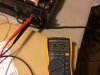
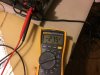
After doing the caps and the joints, I tested with my headphones and got clear sound out of both channels. I then tested the dc offset from the speaker terminals

The left channel measures about -25mv which could be better, but I’ve seen functioning JVC receivers like this with similar values.

The right channel has an offset 370mv. Obviously very high.

I then tried testing the unit using one speaker and testing the channels separately. The left channel preformed just fine and gave decent sound.

Even though it is not recommended to plug a speaker in to a channel with a dc offset that high, but I tried it real quick and ALSO got decent sound quality out of the right channel.


One thing I did notice is when I hooked up the speaker to the right channel (the one with the 370 mv offset) and and pushed in the speaker 1 button, I a subtle but very audible ‘Pop’ come out of the speaker, as mentioned before though the speaker still preformed ok.


The thing about these JVC units is they don’t have a pot to adjust DC Offset, they only have a pot to adjust idle current, which I did adjust to the proper 5mv)


Any one have a suggestion on how I could go about diagnosing why the right channel dc offset is so high?


Here is a link to the amplifier section schematic.

https://drive.google.com/file/d/1l-ZfIp0w4MStdU3mVBANdnqQC34jQ0Xj/view?usp=sharing

I will take another look at the joints and possibly the resistors on the main board when I get the chance.
 

Attachments
  • E8DAD52A-65C3-4E74-B7B5-D1CD680129BD.jpeg
    E8DAD52A-65C3-4E74-B7B5-D1CD680129BD.jpeg
    110.4 KB · Views: 48
  • 57DAB640-8FFB-4807-AFD8-2458CB9C2143.jpeg
    57DAB640-8FFB-4807-AFD8-2458CB9C2143.jpeg
    76 KB · Views: 43
  • 6BD83EF5-BBF4-4341-A44F-CC40D99A4229.jpeg
    6BD83EF5-BBF4-4341-A44F-CC40D99A4229.jpeg
    76.6 KB · Views: 43
Last edited:
Register to hide this ad
Just to be thorough you could confirm that it's a power amp issue
by running the Rx as a separate, ie, connect another preamp.

In such situations with moderate dc offset, people tinker with the
differential pair Q702,Q704, ie, replace with hfe matched pair, but
in this case, 370mV.

You should measure Q702, Q704 b/c/e voltages to ground/chassis just to
make sure all is ok.

You could consider replacing R706(2k) with a VR but I'm thinking this
will just mask the problem of a tired or faulty component. Think you
should hunt down the source of this voltage
 
An update here:


Things were looking ok, but while running a single quick test, I completely disconnected the pre driver board and soon there after, re connected it, my second relay was not clicking. When i checked the voltages on the pre driver pins, I was getting very weird voltages across the pins.

I was getting these weird voltages before when I first got the unit and started testing, and so I thought I fixed them when i re did some of the solder joints.

I then decided to take a working pre driver board off of one of my JVC RX part units to verify if it is the main amp board or the pre driver boards that is giving the issues, when I connected the verified working pre driver card, the relay clicked back on and the dc offset went down to a much more acceptable 15MV.

I then Reinstalled the faulty pre-driver board and turned the unit on. When I did so, the relay clicked and These were the voltages I got on the pins of the faulty board.


Pin 1: 0V
Pin 2: 0V
Pin 3: 0V
Pin 4: 0V
Pin 5: .337V (Same as the dc offset)
Pin 6: -2.024V
Pin 7: 2.692V
Pin 8: -68.5V
Pin 9: 68.5V
Pin 10: 1.770V
Pin 11: 1.045V
Pin 12: -0.013

So it looks like there are at least a couple transistors or resistors that fell out of spec. I remember doing the diode test on all of the pins of the transistors with my multi meter, but none of them tested as a short.

I will have to take a closer look.
 
Last edited:
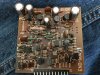
One thing though is if you take a look at the pre driver board it is quite discolored. It definitely seen some heat while it was in use. yet again another reason why we should be putting a small DC fan on these Mid to late 80s JVC units

68558489-B85F-4215-9A8B-25EF907D4F89.jpeg
 
  • Like
Reactions: mbz
I've got the same PCB out of my RX-750V that I bought new in 1987. It is not as well made as the rest of the PCBs. I have been thinking of recreating a new board from the pictures in the service manuals. I got bored and haven't touched it for some time. I was having similar symptoms... voltages on some of the pins weird, popping sounds etc. I think it all comes back to cracks in the PCB traces. By the way, a couple of years ago, I tried ordering the PCB, both stuffed and bare and had my orders cancelled.

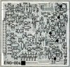
Anyone know how hard it is to make a PCB from a photo like this...

Capture.jpg
 
Yea I was thinking it would be nice if one could at least do some sort of mods to the board to make it last longer. It gets absolutely cooked with out a fan.

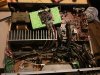
While Using those male to female bread board jumpers I was able to get a better look at the components on the pre driver while the unit is running and I must say that you would swear that Q711 and Q722 were shorted out with the way they would get so hot. I can’t believe they even lasted as long as they did. They will burn your fingers if you touch them.


If there was a way you could get a mini heat sink installed on them, as well as the other transistors, it would be a no brainer
005E265E-E9C2-4201-B6D9-DD5F0B9813DE.jpeg


8057C3FC-9C79-4F46-A756-ACE6E8631801.jpeg
 
On some JVC AVRs, they used the screws on the RCA jacks on the rear panel to complete the ground path. They get loose and you get weird voltage readings. Tighten all the screws on the rear panel.
 
Bumping this thread because I have nearly identical symptoms on an RX-9V which from what I can tell is very similar to the OP's RX-950.

I've reflowed most solder joints on the ENG-004 board, replaced the caps on this board, pulled and tested all transistors on this board using an Atlas DCA (all good) and still have a flaky right channel. It was actually working as expected for a while last night. But today no such luck.

-Matt
 
Last edited:
Quick follow up. I think I may have found the culprit. There are four 2SA1038 transistors, Q705/Q706/Q709/Q710, which all tested good the first time I pulled them. One of them did give me a flaky reading at first, but I figured it was because the leads on my DCA may have been touching. I retested and it passed. Maybe that was actually an indication of a sketchy transistor. In any event, I swapped these all out with the closest sub I had on hand (KSA992) and now things seem to be working perfectly. It's been running for about an hour at a pretty good clip. Bias is stable. DC offset on both channels is < 20mV.

It looks like replacement 2SA1038s are going to be expensive and hard to find (and of unknown quality). I may leave the 992s since they seem to be doing the job and have been recommended in other posts.

This sounds very nice but does get hot. I'll have to get a fan for it at some point.

-Matt

UPDATE: I just tested all four 2SA1308s again and two of them are now open / dead. Mystery solved. Amp is running great. I'll be buying a fan shortly.
 
Last edited:
Great detective work! Those should be great subs for those transistors. I wonder if it would be a good idea to put heat sinks on them. I know there are small ones made for TO92 transistors like avionic linked above.
 
i don't know if i posted it before, but i use a simple wall wart that has an adjustable output voltage so you can regulate the fans speed and noise. i then just spliced some new pc fan to it and it works nice.
 
I've been using a 120mm quiet fan (Enermax) with a 12VDC wall wart plugged into the switched outlet. I put the fan right above the pre-driver PCB to pull air through. I cannot hear it run unless I get right next to it.
 
A friend of mine gave me a great idea last night. He suggested blowing that image from the service manual up to a large size 8 1/2" x 11" or larger. Then using a Sharpie, trace the pattern on transparent plastic. Then scan it back in as a bitmap image. There are ways of importing bitmaps into the programs that can make a PCB gerber file. If I ever get some free time, I may try this.
 
Back
Top Bottom