• The move to the new server is done. There are some software and database maintenance updates in process. This has us passing the hat around to help out. We appreciate any donations. Seriously, even a dollar helps. The payment page may be found here - https://www.audiokarma.org/support.html

KA-7300 Problems

sake

Active Member
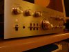
I lucked out and found a KA-7300 for $25 on CL. Unfortunately it has some problems.

As soon as I got it home I plugged in my MP3 player to aux & then my headphones to do some listening. There was some slight static & scratchyness on some of the controls, but nothing major. Unplugged it and cleaned all pots & switches with F5 & D5. I listened some more and was just floored by the liquid sound I was hearing. Amazing amp. Not gonna replace my G-8000, but I think it's the second best sounding piece of gear I own(Yes I'm talking to you MAC 1900).

Then there is the relay driver transistor problem as is touched upon in this thread: http://www.audiokarma.org/forums/showthread.php?t=277328&highlight=ka-7300 I plan on refreshing the power supply board so I placed my order for all the parts listed by EW from Digikey. Offset is somewhat high but will hopefully go down after the refresh(60mv & 70mv).

Now the bad: The other night I disconnected the G-8000 and and inserted the KA-7300 into my main system. After about two minutes, I started getting this loud intermitant popping sound from my right speaker. I quickly shut it off. I then tried a different input and this time only with headphones, popping was still present. It's not a scratchy dirty switch kinda sound, but a hideous arching kinda pop. Some faint, some loud.

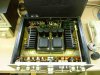
The inside of the amp looks like it once had a drink spilled inside it. I can see dried up tarnished spots from the top down view. Also, there is a bit of thermal paste smeared on the heat sinks near both TA-80W outputs that may have been replaced as a result of the drink. Doubt it left the factory with that much paste where it didn't belong.

So, my question is, should I expect the popping sound to subside once the power supply board & relay are refreshed or do I have another completely seperate issue? And can I expect the offset to lower significantly? Also, it works spectacularly as a pre-amp only. No popping at all, just clear as can be.
 

Attachments

  • P1030496.jpg
    P1030496.jpg
    45.3 KB · Views: 76
  • P1030501.jpg
    P1030501.jpg
    62 KB · Views: 110
Register to hide this ad
Ka 7300

I got rid of mine about 10 years ago. I really miss it. You could flip the power switch off and still hear music for 3 seconds, great power supply, and an excellent preamp, too. :tears:
 
I have the pre-outs sent to a Realistic STA-2000 75wpc at the moment with nothing but incredible sound. Played a couple cds back to back, not a pop.
 
Then the issue is isolated to the 7300 power amplifier.

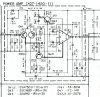
The voltage amp section of the 7300 is quite simple...a differential pair followed by some medium-duty transistors in a VA stage.

Replace all the active devices on both channels...this means the 14V 500mW zener (De1), the differential pair trannies (Qe1 & Qe2), and the VAS trannies (Qe3 & Qe4), as well as all the electrolytic caps on these boards (Ce3, Ce4, Ce5, Ce8, Ce9 & Ce10, and increase Ce5 from 33µf 10V to 220µf 10V).

Qe1 and Qe2 are responsible for keeping DC offset in check, and two closely matched high-gain transistors are called for here. Use the Fairchild KSA992 (Mouser #512-KSA992FBU). They are cheap...order a pile and match a pair as closely as you can.

The other two transistors need to be TO-126 style, but the board layout is EBC. I'd use the Fairchild KSA1220A for Qe4 and the KSC2690A for Qe3. (Mouser #512-KSC2690AYS and 512-KSA1220AYS). The problem here is these devices are center-collector, so you need to familiarize yourself well with the board layout, and do some creative lead-bending to get the new Fairchild devices installed.

Zener PN is 78-1N5244B. You can dig up the electrolytic caps (use decent Nichicon 105°C caps).
 

Attachments

  • KA7300_Amp_single_scat.jpg
    KA7300_Amp_single_scat.jpg
    116.9 KB · Views: 159
Last edited:
Wow! Thanks EchoWars, that should keep me busy.

I personally haven't taken the restoration of any of my gear this far, but have wanted to try for awhile now. I probably wouldn't have decided to do the relay board myself but after seeing you list the actual part #s in the other thread, I thought, I should be able to do this.

I'll place a new order once I get in there and read the cap values. I'm sure I'll have a few more questions once the parts arrive and I start the work.

Thanks again.
 
There's nothing hard about this as long as you download the data sheets for the new transistors and make sure you understand which lead is which, and take a similar serious attitude towards studying the amplifier PC board till you're 110% sure that you know which lead goes where.

The zeners and the electrolytic caps also are polarized, so it also matters which way they are installed. Get it right the first time, and make yourself a dim-bulb tester for your first power-up after the work. :yes:
 
Update:

Ok, the parts came for the power supply board. I got the relay, caps & diode replaced.

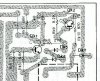
My question on installing the transistor is, should the two points in the highlighted areas in the the picture be bridged? The rectangle looks as if it definitely should, but the circled areas are hard to interpret. The picture is the back of the board with the old part still attached. I just want to be sure so that I'm not shorting two areas that should not be connected.

Also, based on looking at the data sheet and the markings on the board, this is an an ECB layout, unlike the power amp boards, therefore I don't have to do any twisting of leads to install the transistor?
 

Attachments

  • TS.JPG
    TS.JPG
    22.1 KB · Views: 96
If I am unsure about a bridged solder joint, I completely desolder the leads and look at the traces underneath.
 
I would have hoped you'd have already sprung for the service manual by now. It would answer your question about the foil traces. See attached pic.

As far as the transistor, it's always helpful to mention WTF transistor you're talking about. But, assuming you refer to Qk2, the relay driver transistor, then the original is a center-collector part, and the board layout is designed to accept it that way.

99% of Japanese transistors are arranged as center-collector, and Kenwood PC boards are set up to receive them that way. The amp board is unusual in that two of the transistors apparently were going to be center-base parts at one time. Nothing to be done about it except to find the neatest way you can to arrange the leads without shorting them.
 

Attachments

  • KA7300_PS_Foil.jpg
    KA7300_PS_Foil.jpg
    106 KB · Views: 90
I'd just like to thank you EchoWars for your insight and knowledge that has helped me immensely through this project so far. The power supply board rebuild went well. I was able to use my newly built dim bulb tester and a dim bulb was a very welcome sign.

On to the power amp boards. I'm about to place my order from Mouser and was wondering about what I saw in this thread: http://www.audiokarma.org/forums/showpost.php?p=597666&postcount=3 where you replaced the stock .47uf input cap with a 1.5µf Matsushita metal polypropylene cap. Would this Mouser part# 594-2222-368-45155 be OK to substitute? I plan on going with Nichicon UPW series for the rest of the caps.
 
Your selected cap is a polyester cap. If I was going to the trouble to replace the stock cap I'd want a good metalized polypropylene. I'd leave the stock cap in place till I could find one that made it worth the trouble. I cannot find one at Mouser (those square plastic caps that Mouser has plenty of, have very short stubby leads and you probably won't find a way to make one fit).
 
Qe1 and Qe2 are responsible for keeping DC offset in check, and two closely matched high-gain transistors are called for here. Use the Fairchild KSA992 (Mouser #512-KSA992FBU). They are cheap...order a pile and match a pair as closely as you can.

Alright, my parts arrived from Mouser today.

I have to ask how to go about measuring the Fairchild KSA992 parts as instructed. I have DMM as I'm pretty sure that's used somehow. I bought 40.
 
My meter(Micronta model 22-185a) has a diode tester, but no transistor setting that I can see. I'm gonna have to go the long painful route it looks like. I mean once I understand how. Worse case I buy a new meter I guess.
 
My meter(Micronta model 22-185a) has a diode tester, but no transistor setting that I can see. I'm gonna have to go the long painful route it looks like. I mean once I understand how. Worse case I buy a new meter I guess.

Buy a new meter it is nice to have two meters when setting bias etc.
 
I have three, and find myself constantly needing a fourth... :scratch2::nutz:

The one I linked to at PE is a special at $20 + ship. There's lots better ones out there, but if you're on a budget...
 
A friend borrowed a meter from work that has the ability to measure Hfe so I was able to get some values on the Fairchild KSA992. I measured 20 of them and came across four that read 380 Hfe. I figured that was a close match for the job. I then completed the work on the power amp boards, passed the dim bulb test and everything sounds great. :banana:

After letting the unit play for about 90 minutes connected to headphones and my mp3 player I decided to check offset values. Expecting them to be lowered, they have actually gone up. Left is now 60mv & right is up to 80mv. Can I expect the values to drop after some burn in time or do I have another problem?
 
Apparently, the new transistors have lower gain than the old ones. Good high-gain transistors with a center-collector lead are hard to find. I would have recommended the Zetex ZTX795A (commonly with gains close to 600), but they are harder to use because of the center-base layout.

Getting good offset numbers on the 7300 is a pain, which is why I added a servo to one 7300 as an experiment. Worked pretty well. http://www.audiokarma.org/forums/showthread.php?t=61639 (sorry about the missing pics, but some are still there).

If you want to try using the Zetex transistors, you can probably lower the offset more, But they are expensive ($1+ each). But with this amp, 50mV or so seems to be about the best you can hope for.

On the plus side, your popping sound is gone, I assume.
 
Back
Top Bottom